
Helicopter Practice
Modifications to the Schlüter Bell 222 and Super-Heli-Baby model kits
Modular helicopter kits are well-designed and proven. However, the manufacturer doesn’t just supply these kits for our enjoyment; he runs a business that must generate a profit. Therefore, various parts are designed to perform their function well but do not achieve the absolute maximum in terms of stability and durability. That would drive up costs so high that it would put the company at a disadvantage compared to the competition.
A model builder with knowledge of metalworking can save himself a lot of trouble by identifying a design’s weak points and eliminating them before a failure occurs. With helicopters, a defect almost always results in at least a crash, if not a danger to the pilot or spectators. I want to show here where improvements can be made and what effort is required.
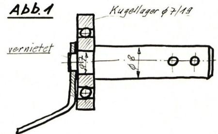
First, there’s the lever for collective pitch adjustment on the Super-Heli-Baby and the Bell 222. This lever is riveted to the blade shaft—that’s the weak point. Under the influence of vibrations, crashes, or simply due to the forces involved in blade adjustment, the rivet connection loosens, and suddenly a rotor blade has a completely different angle of attack. This greatly reduces controllability. Every owner of a Super-Heli-Baby or a Bell 222 has surely experienced this situation several times.
Because of the use of ball bearings with an inner diameter of 7 mm and needle bearings with an inner diameter of 8 mm, the blade pitch lever in the original design cannot be welded or brazed. Otherwise, the ball bearing would overheat. For this reason, the ball bearing is slid into place, and then the blade adjustment lever is riveted. Fig. 1 shows the original design.
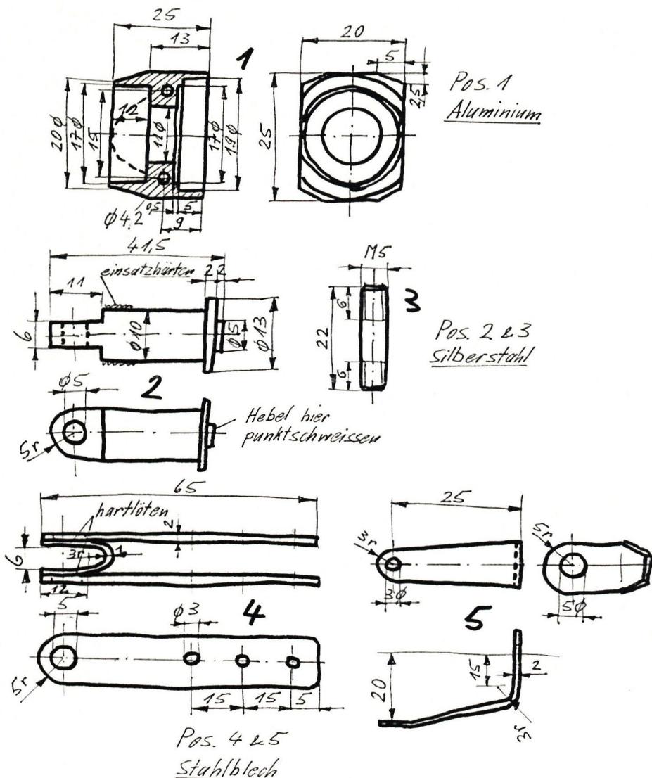
The improvement consists of using ball bearings with a diameter of 19/10 instead of the 19/7 ones. They correspond to Schlüter catalog number 456 and are used as the main rotor bearings on the Bell 222. In Switzerland, they are available from Miniatur Kugellager Biel under type UL 1019 for 6.50 Swiss francs (June 1979). A new blade adjustment shaft, as shown in Fig. 2, allows a blade adjustment lever to be welded on and the ball bearing to be slid onto it afterward.
If you want to be absolutely sure, you can also replace the needle bearing with one that has an inner diameter of 10 mm. It is available with the dimensions Ø 17/10 × 12 (width) under the model number DKN 10/12 from SRO in Zurich for Fr. 6.65. This design allows for a modern, swiveling blade mounting, as is featured on the Kavan Jet-Ranger and the Graupner Bell 222. Fig. 3 shows the parts required for this. Anyone who decides on this solution should also fabricate the side plates No. 551 from the Schlüter catalog using 1.5-mm steel sheet from the Schlüter catalog and select the dimensions so that M4 screws can be used instead of the M3 mounting screws for the aluminum blade adjustment bearings. Another weak point in the design of Schlüter’s Bell 222 is the
This design offers the option of creating a modern, swiveling blade mounting system, as featured on the Kavan Jet-Ranger and the Graupner Bell 222. Fig. 3 shows the parts required for this. Anyone who decides to use this solution should also fabricate the side plates No. 551 from the Schlüter catalog from 1.5-mm sheet steel and select the dimensions so that M4 screws can be used instead of the M3 mounting screws for the aluminum blade adjustment bearings. Another weak point in the design of Schlüter’s Bell 222 is the clamping screws for the tail rotor drive shaft. The 1.5-mm-diameter steel wire has a ground surface at both ends. An M3 Allen set screw in the gear wheels clamps the wire securely through the hubs. At the front, the set screw can be secured with Loctite or a similar chemical substance. At the rear, this isn’t as easy to do because the enclosed tail rotor gearbox housing must be inserted into the tail tube as a single unit. And since it’s filled with grease, the set screw will no longer be grease-free, so the chemical lock will no longer hold. Sooner or later, the adjustment screw will loosen slightly and the tail rotor drive will fail. This doesn’t necessarily mean a crash. If you keep your cool, you can still save the helicopter, which is now spinning wildly but relatively stably. The rotation creates additional drag, causing the model to descend. Carefully adjusting the pitch upward stops the descent, and gently reducing the pitch allows the helicopter to descend slowly. With a bit of luck, nothing will break, and if it does, it’s likely only the rotor blades that will be damaged. But even that is a cost. My suggestion for improvement is shown in Fig. 4. New axles for the bevel gears are made from 5 mm diameter silver steel. The bevel gears are secured to the axle with M3 Allen screws and a chemical lock. Outside the
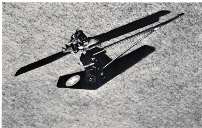
Improved tail rotor and tail skid on the Bell 222. With new axles for the bevel gears and soldered-on adjustment rings ...
...and a tail skid bent from spring steel.
Improved landing gear mounting using aluminum reinforcement brackets and spring steel skid supports. The bearing seats consist of soldered adjustment rings, each containing two M3 threads offset by 90°. The tail rotor drive shaft is provided with two grinding surfaces offset by 90°, and the rest should be clear. To assemble, first tighten the screws on the tail rotor and then feed the wire into the hole at the front of the tail tube.
Finally, the Bell 222’s tail skid isn’t exactly a masterpiece of design either. If, under load—and that’s actually why it’s there—it rotates around its single mounting screw and ends up getting caught in the tail rotor, that’s at the very least undesirable. But the tail rotor blades damaged in such an incident cost money, and you can save yourself that expense by bending a tail skid out of spring steel that looks something like Fig. 5. It’s secured with two screws and can withstand quite a bit.
Securing the landing gear with a single M3 screw is also a bit wobbly in the long run. This can be remedied with 20/20/2 aluminum reinforcement brackets, which are screwed to the chassis.
If you’ve had enough of the bent skid mounts made from flat aluminum profile, you can make your own from 5-mm spring steel wire. They are attached using brazed brass pieces as shown in Fig. 6. Finally, one more improvement to the Super-Heli-Baby. Flawless “crash-survivor” rotor blades from the Bell 222 can be used. The blade depth is greater than that of the Clark-Y profile used on the standard Baby rotor. This provides more lift. And since the ratio of lift to drag coefficient is higher with the symmetrical profile of the Bell 222, the Super-Heli-Baby modified in this way requires even less power. Give it a try!


News from HEBU

EURO CONTEST GLIDER ACRO TOUR AUSTRIA 2026

TEAM MANAGER "THIS" BOSSHARD
 Rodito Nussbaumer

YOU KNOW WHAT I MEAN? 125 YEARS OF THE SWISS AERO CLUB
 Emil Giezendanner

F3A EUROPEAN CHAMPIONSHIPS IN ST-MACAIRE, FRANCE
 Matthias Bosshard

HORIZON HOBBY/LEMACO NEWS: MICRO OV-10 BRONCO 645 MM BY E-FLITE

PRIDE AND GOOD IDEAS
 Markus Nussbaumer

BY YOUTH, FOR YOUTH
Lorena Betschen
34th HAHNENMOOS ALPINE MODEL AIRPLANE CAMP
Res Dauwalder
TRY-OUT DAY AT MFV WETTINGEN
Urs Keller
52. 2026 ALPS CUP
Emil Giezendanner
TWIN TOWN PARTNERSHIP
Wolfgang Voeller
ATOM, THE NEW DOUBLE-DECKER FROM CPLR
Matthias Bosshard
CORSAIR F4U – A WARBIRD WITH A MEMORABLE LOOK
Jürgen Rosenberger, Jürgen Prinz
SUMMER FUN 2026 AT MG USTER
Martin Wunderli
What's New at Leomotion.com

THE PC-21 STORY
Emil Giezendanner
COUPE DES ALPES – OBSERVE AND LEARN
Rodito Nussbaumer
SMALL, MODEL-LIKE SAILBOATS
Res Dauwalder
WELCOME, NEW MEMBER!
Andrea Bolliger
FREE FLIGHT IN THE MIDDLE OF SUMMER
Urs Muntwyler
INSIGHTS INTO THE HISTORY OF SEAPLANES

NEWS FROM HEBU
 Julia Bucher

FROM 0 TO 100
Markus Nussbaumer
MEMORIES
Wolfgang Völler
NOS REGION – A HUB FOR ELECTRIC AVIATION
Emil Giezendanner
DO YOU KNOW WHAT I MEAN IN THE LAND OF SMILES?
Emil Giezendanner
A SPECTACULAR F3A WORLD CUP IN THE PRINCIPALITY OF LIECHTENSTEIN
Emil Giezendanner