
Why Do Model Aircraft Controllers Overheat?
The currents and voltages in electric model aviation are getting higher and higher. The power density of LiPo technology has exacerbated the problem of overheating ESCs.
In the following, we will discuss the electrical operation of brushless motors and modern controllers, identify the causes of power loss in the controller, and provide recommendations for preventing thermal overload.
From an electrical engineering perspective, the windings of an electric motor are coils or, more precisely, inductive resistors. In a coil, the current cannot
flow freely; instead, voltage spikes occur, the magnitude of which increases with the coil’s inductance and the current with which it was charged. These spikes can cause damage due to overvoltage. Coils operated with direct current are therefore often protected by a free-wheeling diode (Schottky diode), which, when the circuit is switched off, allows the current to continue flowing through a diode connected in anti-parallel to the coil, allowing it to flow freely and dissipating the stored magnetic energy, thereby reducing the voltage spike.
change abruptly. If a DC voltage is suddenly applied to a coil, an asymptotic rise in current follows (e-function curve). If the voltage is suddenly turned off, the current continues to flow and generates a reverse voltage.
A sudden interruption of the coil current leads to voltage
When a coil is operated at AC voltage, the current always lags behind the voltage by 90°. When a current flows through a coil (winding), a magnetic field is generated.
A brushless—or electronically commutated—motor is a hybrid of
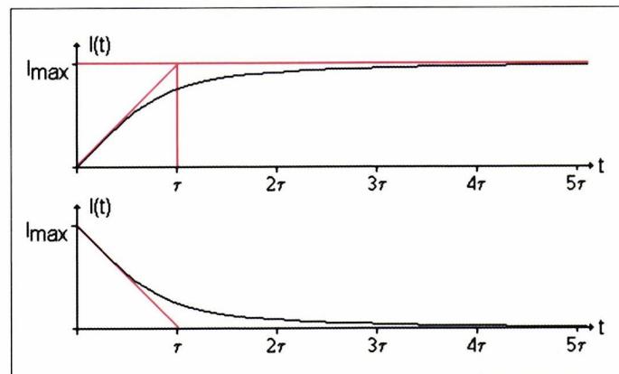
Current flow in a coil when the DC voltage is turned on (top) or off (bottom).
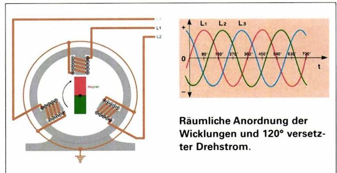
Spatial arrangement of the windings and 120°-staggered three-phase current.
Three-phase synchronous motor and DC motor. Let’s consider the simplest case of a brushless motor: the stator has three windings (coils) spatially offset by 120°, and the rotor has a two-pole permanent magnet. The current through the winding generates a magnetic field. If the motor’s three windings are each driven by a sinusoidal current that is phase-shifted by 120° (called three-phase current), a rotating magnetic field is generated. This rotating magnetic field then pulls the stator’s permanent magnet along with it—the motor begins to rotate.
This already highlights a fundamental problem with brushless motors: the rotating magnetic field of the stator and the rotational speed of the rotor must always be the same—that is, synchronized—otherwise the motor will stop or fail to start at all.
To better understand how a controller works in the partial-load range later on, we need to briefly discuss
pulse width modulation. In pulse width modulation (PWM), the on and off times of a square-wave signal are varied while maintaining a fixed fundamental frequency, resulting in different average voltages ( $U_m$ ).
As is easy to see, the following equation applies to the average voltage:
$$U_m = U_{off} + (U_{on} - U_{off}) \cdot \frac{t_{on}}{t_{on} + t_{off}}$$
You can think of this as a light switch that is turned on and off very quickly: If the off time is longer than the on time, the light appears dimmer on average ($U_m$); however, if the on time is longer than the off time, the light appears brighter on average (this is how low-loss dimmers work, by the way).
The major advantage of PWM for motor control is its high efficiency and low power loss. The frequency used is typically in the range of a few tens of kHz.
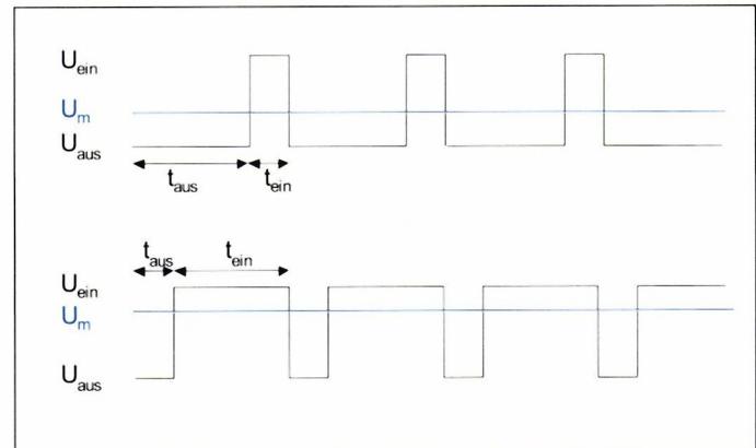
Different pulse widths at the same frequency produce different average voltages.
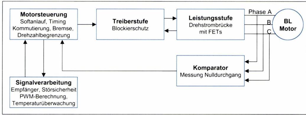
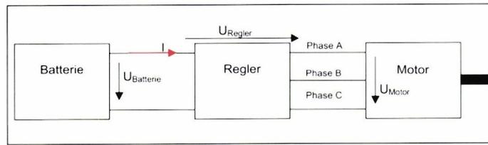
Block diagram of a brushless controller.
Before we go into more detail about the controller, we need to briefly explain how an FET (field-effect transistor) works. The principle behind the FET has been known since the 1920s, but it wasn’t until silicon technology was mastered that it could be put into practice.
An FET has three terminals: the source, the drain, and the gate. An electric field—generated by a small control voltage between the gate and source—allows the conductivity (resistance) between the source and drain to be controlled with virtually no power consumption.
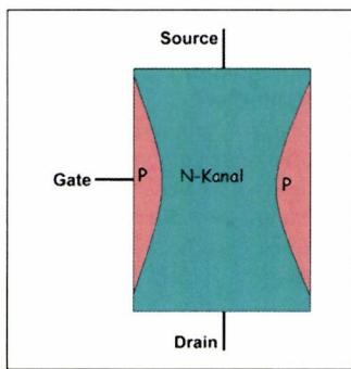
For our application in the controller, we use the FET like a switch: fully on (switch closed) or fully off (switch open).
As we saw earlier, the brushless motor needs to be powered by a three-phase sinusoidal voltage source. In model building, however, we have a rechargeable battery (DC voltage source) at our disposal. Therefore, the controller must generate a voltage that approximates a sine wave. This is achieved using a half-bridge (= $\frac{1}{2}$ three-phase bridge) consisting of two FETs (field-effect transistors).
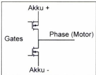
Principle of a three-phase bridge for a single motor phase.
Each terminal of the motor can be connected directly to the positive terminal (A+) or the negative terminal (A-) of the battery, or it can be left open (with both FETs fully turned off).
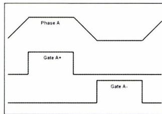
Phase A with the corresponding control voltages (Gate A+ and A-) of the FETs.
One such half-bridge is required for each of the motor’s three phases: A, B, and C. By carefully controlling the six FETs, three-phase current can be approximated. The three phases are phase-shifted by 120°.
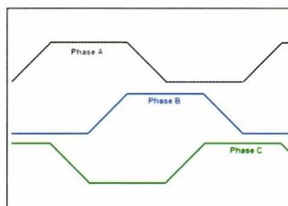
Approximated (sinusoidal) three-phase current.
The two states—phase at the positive terminal and phase at the negative terminal—are clearly visible. In between, the phase is open for one-sixth of a motor revolution (60°) at a time. During these intervals, the voltage is not a constant half of the battery voltage, as one might expect, but rather rises or falls. This is because the rotor is rotating and induces a voltage in the open winding. This phenomenon is exploited to design the control loop. When the rotor runs in sync with the rotating field, the
half the battery voltage is reached approximately in the middle of the commutation state after 30°. If the rotor is too fast, it reaches half the battery voltage earlier; if it is too slow, it reaches it later. Therefore, one must measure the zero-crossing times and can then determine whether the rotating field is running in sync with the motor and, if necessary, make the appropriate corrections. This is the principle of “sensorless” control—that is, without special sensors that provide information about the rotor’s position.
When measuring the zero-crossing using the comparator, the principle of timing comes into play. In practice, for stable motor operation, the zero-crossing must occur slightly later than 30° after the commutation change—for example, 35°. This delay (35°–30°=5°) is commonly referred to as timing. The motor achieves its best efficiency at a timing that is nearly zero. With some controller models, the control does not function well enough to achieve this condition with every motor. In that case, a larger timing must be used.
In practice, 5° has proven effective for a wide variety of motors. However, the 5° setting applies only to motors with sinusoidal flux distribution and relatively low loads. Hacker, Kontronik internal-rotor, and Lehner motors are sinusoidal motors that are subjected to heavier loads in practice and therefore operate more optimally with different timings.
Well, that was easy, wasn’t it? But now things are getting a little more complex.
Since the motor is now supposed to draw less current for partial-load operation at the same battery voltage, we’ll make use of the principle of pulse-width modulation (PWM). We simply “chop up” the control voltage of the FETs, causing the motor phase to receive less current on average.
This gives us a chopped motor phase that still closely follows a sine wave. Pulse-width modulation reduces the average voltage (phase A) and, consequently, the current and rotational speed.
Pulse-width-modulated three-phase bridge with averaging (Phase A).
Voltages are present at the controller, and currents flow through it. Where voltage and current occur simultaneously, electrical power (= voltage × current) is converted into heat. The controller can only dissipate a certain amount of power as heat into its surroundings. If this limit is exceeded, the controller continues to heat up until it shuts itself down due to overheating (thermal overload protection) or burns out (no thermal overload protection).
The following sections outline the causes of power loss in the controller and how to counteract them:
In general, care must be taken to ensure that the controller
- is located in a “draft” so that the generated heat is efficiently dissipated.
- is correctly sized in terms of current and number of cells.
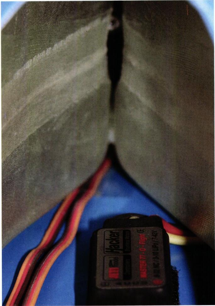
Practical experience has shown that air leakage on the “suction side” of an impeller is not a problem, especially if the hole is centered relative to the spinner. This allows for a simple yet highly efficient cooling solution in models with a Y-tube:
If a hole is placed on the suction side of the impeller exactly where the Y-tube joins, the speed controller located in front of it receives forced cooling. It’s best to enclose the controller in a tube that is centered relative to the spinner at the Y-tube junction. Combined with a NACA opening in the nose section, this creates an efficient, cool airflow that circulates not only around the controller but also around the batteries.
If it’s not possible to place the ESC inside the intake tube, cooling fins can be used
| Location of Loss | Reason | Reduction due to |
|---|---|---|
| FET three-phase bridge (and PCB losses) | When the FET is “turned off,” the current cannot follow immediately due to the subsequent coil in the motor. As a result, a voltage and current are present across the FET for a short time = power loss. Under full-load operation, this power loss is not a major concern. However, during partial-load operation, the switching events are suddenly multiplied by the PWM (chopping), and thus the power loss increases dramatically! At low inductance (few turns), high current spikes occur at low PWM frequencies. | For high motor inductance (high number of turns): Select the lowest PWM frequency on the controller. For low motor inductance (low number of turns): Determine the optimal PWM frequency through trial and error. Avoid throttle positions of 70% ... 99.9%; prefer 100% and 0 ... 70%. |
| Long battery cables | Due to the PWM, long battery cables also act like coils, which places an additional load on the controller’s input. | Use short battery cables; an extension cable between the controller and the motor is possible. |
| Free-wheeling diode | Prevents voltage spikes during the falling edge of the motor phases by “dissipating” the magnetic energy. | (Cannot be directly controlled, as they are sometimes built into the controllers) |
| BEC | The ESC must provide a constant voltage for the receiver. The current from the BEC for the servos causes the ESC to heat up even more. | Consider omitting the BEC and using the receiver battery or a separate battery switch instead. |
When designing a model-making motor, the number of cells and the maximum expected current are usually known. The next step is to select the right controller (without a finned heat sink) for this application—in such a way that you don’t fall into the “overheating trap”!
The well-known 80-20 rule can also be used here as a rule of thumb:
Operate the ESC at a maximum of 80% of the continuous current (20% reserve) and at no more than 80% of the maximum allowable number of cells (20% reserve) (cumulative!)
Example 1: max. expected current 50 A on 7S LiPo cells
According to the rule of thumb, you should select a controller that can handle a continuous current of at least 62.5 A and can be operated with 9 LiPo cells (exactly 8.75). (e.g., Master 77-O-Flight).
But some people may wonder: How can I power a motor with 10S LiPo cells if a ESC is rated for a maximum of 10 LiPo cells? ... that’s why it’s “cumulative”: If the reserve cannot be maintained for one of the two key parameters, the other value must have an even higher reserve.
Example 2: Max. expected current 50 A on 10s LiPo cells
. Since there are currently only ESCs without heat sinks available for up to 10 LiPo cells—and thus no reserve is possible—a higher current reserve of 40% (20% + 20%) must be factored in for the current. Thus, the 50 A current may only be 60% of the continuous current. Our controller must therefore be able to handle a continuous current of at least 83.4 A. (e.g., Master 90-Acro)
Controllers with finned heat sinks (not to be confused with cooling plates!) dissipate heat much more efficiently. This usually eliminates the 20% margin. For example, in the case of Example 2 above, a Schulze future-32.55K (10 LiPo, $I_{\text{continuous}}$ 55 A, K = with finned heat sink) can be used in a well-ventilated area.
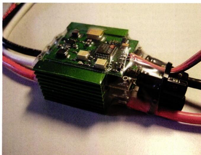
As a general rule, the total length of the cables inside the battery and between the battery and the speed controller’s circuit board must not exceed the manufacturer’s specifications! Cables act as inductors and, in pulse-width-modulated (PWM) speed controllers, cause voltage spikes of several hundred volts, which must be absorbed by the externally mounted capacitors (low ESR!) and internal protective circuits. The longer the cables, the more harmful energy the protection circuits in the speed controller/regulator (which may not be rated for continuous load) must handle. As a result, they become hotter than would be expected based solely on the losses listed in the table above.
Therefore, it is definitely advisable to use a speed controller designed for 14 LiPo cells (= 40 nickel cells, e.g., Schulze future-40.160xx) when using longer connection cables.
However, since speed controllers rated for up to 10 LiPo cells are currently more affordable and thus offer no margin for safety, a safety margin must be created in another way.
One way to do this is by installing additional operating voltage capacitors with low internal resistance (low-ESR capacitors used in switching power supplies).
On the other hand, a higher current reserve of 40%
(20% + 20%) must be factored in to minimize losses (= less heat) through the FETs. Only then is there a chance that the heat generated by the protection circuits will remain within acceptable limits and not lead to thermal overload of the driver/controller.
Incidentally, according to the manufacturer, voltage spikes are the most common “cause of failure” for the driver/controller, along with unreliable contact due to dirty and/or worn connectors, which can then lead to incorrect commutation in a brushless system and, in turn, to unexpectedly high voltage spikes.
Proper programming, efficient cooling, a healthy “oversizing” of the controller, and careful use of the throttle lever prevent annoying engine shutdowns due to controller overheating, even at higher outside temperatures:
- For motors with a high number of turns, select the lowest possible PWM frequency
- For motors with a low number of turns, the optimal PWM frequency must be determined through trial and error.
- Mount the controller in a “drafty” location.
- Follow the 80-20 rule of thumb when sizing controllers without finned heat sinks.
- Observe the maximum permissible cable length within the battery and between the battery and the controller
- Prefer throttle positions of 0 ... 70% and 100%
electric power – what else?!


News from HEBU

TEAM MANAGER "THIS" BOSSHARD
 Rodito Nussbaumer

YOU KNOW WHAT I MEAN? 125 YEARS OF THE SWISS AERO CLUB
 Emil Giezendanner

HORIZON HOBBY/LEMACO NEWS: MICRO OV-10 BRONCO 645 MM BY E-FLITE

PRIDE AND GOOD IDEAS
 Markus Nussbaumer

34th HAHNENMOOS ALPINE MODEL AIRPLANE CAMP
Res Dauwalder
TRY-OUT DAY AT MFV WETTINGEN
Urs Keller
F3A EUROPEAN CHAMPIONSHIPS IN ST-MACAIRE, FRANCE
 Matthias Bosshard

52. 2026 ALPS CUP
Emil Giezendanner
ATOM, THE NEW DOUBLE-DECKER FROM CPLR
Matthias Bosshard
SUMMER FUN 2026 AT MG USTER
Martin Wunderli
What's New at Leomotion.com

COUPE DES ALPES – OBSERVE AND LEARN
Rodito Nussbaumer
TWIN TOWN PARTNERSHIP
Wolfgang Voeller
BY YOUTH, FOR YOUTH
Lorena Betschen
CORSAIR F4U – A WARBIRD WITH A MEMORABLE LOOK
Jürgen Rosenberger, Jürgen Prinz
SMALL, MODEL-LIKE SAILBOATS
Res Dauwalder
WELCOME, NEW MEMBER!
Andrea Bolliger
FREE FLIGHT IN THE MIDDLE OF SUMMER
Urs Muntwyler
EURO CONTEST GLIDER ACRO TOUR AUSTRIA 2026

INSIGHTS INTO THE HISTORY OF SEAPLANES

THE PC-21 STORY
Emil Giezendanner
NEWS FROM HEBU
 Julia Bucher

FROM 0 TO 100
Markus Nussbaumer
MEMORIES
Wolfgang Völler
NOS REGION – A HUB FOR ELECTRIC AVIATION
Emil Giezendanner
DO YOU KNOW WHAT I MEAN IN THE LAND OF SMILES?
Emil Giezendanner
A SPECTACULAR F3A WORLD CUP IN THE PRINCIPALITY OF LIECHTENSTEIN
Emil Giezendanner