
Electronics Lab – Styrofoam Saw
Recently, various model-making magazines have covered the topic of “thermal saws.” Some of the proposed circuits for controlling the cutting wire’s heat were quite complex. However, this report aims to show that there is an even simpler and more affordable way to achieve the same results without sacrificing the convenience of stepless heat regulation.
In an issue of the magazine “Modell” published by Villinger-Verlag, a suggestion was made—for the sake of simplicity—to control the cutting coil using a standard dimmer. Although it is briefly noted that the dimmer should be suitable for inductive loads, as I have observed in various discussions, people don’t give this much thought. I’ve even been told: “Then I’ll just connect the cutting wire directly to the dimmer.”
Why does the dimmer need to be suitable for inductive loads? A transformer is an inductor, not a “light bulb.” When switching inductive loads, switching spikes occur that can reach voltages many times higher than the original voltage; these then contaminate the power grid as interference signals. After all, the dimmer doesn’t just turn the transformer on once, as we do with a switch, but a hundred times per second. These so-called interference spikes also throw the dimmer out of sync, and then people wonder why fuses are blowing one after another or why the circuit is “acting up.”
As an electronics technician, I place great importance on personal safety. For this reason, I strongly advise against controlling the heating wire directly with the dimmer. As a reminder, I’d like to point out that voltages above 50 V are life-threatening.
So what can you do to get a good, affordable device? Department stores offer car battery chargers for very little money. This way, you can get an affordable device that has been tested and approved by the SEV for personal safety. What happens after the transformer is no longer of concern to the relevant authorities. So now you have the transformer, the housing, an ammeter to monitor the cutting wire’s temperature, a rectifier, and a circuit breaker. All you need now is a suitable circuit that operates on a voltage of approximately 18 V DC.
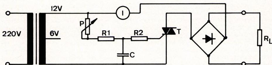
P = 5 kOhm potentiometer, R1 = 100 Ohm ¼ W resistor, R2 = 22 Ohm ¼ W resistor, C = 0.1 uF 40 V plastic film capacitor, T = Q 4004 triac from ECC, 4 A/240 V, model with built-in trigger diode in a Thermotap housing.
Charger for conversion: Must be suitable for a 12-V car battery. Charging current = 4 A, e.g., Miocar charger for CHF 38.00 at Migros.
The circuit shown in the diagram works flawlessly up to a transformer voltage of 12 V. It is connected between the secondary output and the rectifier. The cost of the components is low, and the few components fit easily on a scrap piece of a Veroboard perforated board. The triac is screwed directly—and in an insulated manner—onto the metal housing of the former charger, or better yet, onto a separate heat sink. The advantages of the modified charger are obvious. More important than the low cost—including that of the charger—are operational reliability and personal safety. The secondary control not only ensures adequate protection but also prevents the
mains supply is not contaminated with inductive voltage spikes. With this control method, the circuit is purely resistive, meaning that switching spikes do not occur in the first place.
If the resulting hum is bothersome, you can connect a 2200 uF/40 V capacitor across the output terminals. Anyone who is reluctant to do the work involved in the conversion can purchase a ready-made unit from me for Fr. 85.
My address is:
Klaus-Dieter Preiss
Baumgarten 6, 8630 Tann-Rüti
Now all that’s left for me to do is to wish everyone success with their builds and a great flying season.
K.-D. Preiss, Best regards, Hinwil


News from HEBU

TEAM MANAGER "THIS" BOSSHARD
 Rodito Nussbaumer

YOU KNOW WHAT I MEAN? 125 YEARS OF THE SWISS AERO CLUB
 Emil Giezendanner

F3A EUROPEAN CHAMPIONSHIPS IN ST-MACAIRE, FRANCE
 Matthias Bosshard

SUMMER FUN 2026 AT MG USTER
Martin Wunderli
TRY-OUT DAY AT MFV WETTINGEN
Urs Keller
52. 2026 ALPS CUP
Emil Giezendanner
BY YOUTH, FOR YOUTH
Lorena Betschen
ATOM, THE NEW DOUBLE-DECKER FROM CPLR
Matthias Bosshard
CORSAIR F4U – A WARBIRD WITH A MEMORABLE LOOK
Jürgen Rosenberger, Jürgen Prinz
SMALL, MODEL-LIKE SAILBOATS
Res Dauwalder
What's New at Leomotion.com

TWIN TOWN PARTNERSHIP
Wolfgang Voeller
EURO CONTEST GLIDER ACRO TOUR AUSTRIA 2026

INSIGHTS INTO THE HISTORY OF SEAPLANES

34th HAHNENMOOS ALPINE MODEL AIRPLANE CAMP
Res Dauwalder
WELCOME, NEW MEMBER!
Andrea Bolliger
HORIZON HOBBY/LEMACO NEWS: MICRO OV-10 BRONCO 645 MM BY E-FLITE

FREE FLIGHT IN THE MIDDLE OF SUMMER
Urs Muntwyler
COUPE DES ALPES – OBSERVE AND LEARN
Rodito Nussbaumer
PRIDE AND GOOD IDEAS
 Markus Nussbaumer

THE PC-21 STORY
Emil Giezendanner
NEWS FROM HEBU
 Julia Bucher

FROM 0 TO 100
Markus Nussbaumer
MEMORIES
Wolfgang Völler
NOS REGION – A HUB FOR ELECTRIC AVIATION
Emil Giezendanner
Have you almost forgotten about aircraft that take off and land vertically?
Emil Giezendanner
DO YOU KNOW WHAT I MEAN IN THE LAND OF SMILES?
Emil Giezendanner