
Flying Scanner
At model airfields, it is not uncommon for flight operations to be disrupted on certain channels or in specific areas of the airspace.
To improve flight safety, the SMV’s Airfields Department has initiated a search for a technical solution to analyze these problems. The idea is to implement in-flight frequency monitoring.
The starting point was the SMV’s scanner case, which is used at air shows. This case is equipped with two scanner receivers—one for 35 MHz and one for 40 MHz—whose output signals are transmitted via radio to a laptop for display, allowing the current radio situation to be viewed at any time.
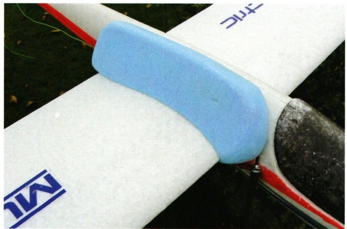
A lightweight scanner receiver, coupled with a transmitter module (868 MHz), is powered by a small rechargeable battery. The entire setup is packed into a block of Styrofoam and mounted on the wing of an Easy-Glider. The receiving antenna is routed in the same way as on models with interference (usually stretched toward the rear of the fuselage). The transmitting antenna extends downward in front of the wing. The model is controlled using a 2.4-GHz system, so there is no mutual interference between the scanner’s 35- or 40-MHz antennas and the flight receiver.
On the ground, the scanner’s measurement signals are received and transmitted to a laptop via the serial interface. The same software used in the scanner case visualizes the data, allowing a flight assistant to monitor the measurements in real time and provide the pilot with appropriate flight instructions. At the same time, the signals can be saved for later analysis.
This makes it possible to detect external interference—which is primarily visible from the model aircraft—and, if necessary, to locate and attempt to resolve it using near-field measurements on the ground.
It is also possible to identify dead zones, i.e., locations in the airspace where, due to multipath propagation in the terrain, radio signals cancel each other out because they travel different distances and reach the model with varying delays, which can lead to the cancellation of radio frequency signals in the area.
Once such a situation has been confirmed, remedial measures can be sought, such as relocating the transmitter or adjusting the direction of the transmitter antenna. However, it could also mean that, at certain airfields, certain channels are no longer used in the interest of pilot and environmental safety.
Visualization of the measured signals on the laptop.
This means that for unresolved cases, a system is now available that can be requested as needed. If necessary, additional measuring devices such as spectrum analyzers and direction-finding equipment can also be used. To resolve interference issues, it is important to note in which flight sector, in which direction, at what altitude or observation angle, and at what times interference was observed. This allows for more targeted measurements.
The system was designed and built by RF specialist Paul Rudolf, MG-HW. He is also available for measurements and consultations.
Anyone in need of assistance should contact Adrian Egenberger, who is responsible for the Airfields Division.


News from HEBU

TEAM MANAGER "THIS" BOSSHARD
 Rodito Nussbaumer

YOU KNOW WHAT I MEAN? 125 YEARS OF THE SWISS AERO CLUB
 Emil Giezendanner

F3A EUROPEAN CHAMPIONSHIPS IN ST-MACAIRE, FRANCE
 Matthias Bosshard

SUMMER FUN 2026 AT MG USTER
Martin Wunderli
TRY-OUT DAY AT MFV WETTINGEN
Urs Keller
52. 2026 ALPS CUP
Emil Giezendanner
BY YOUTH, FOR YOUTH
Lorena Betschen
ATOM, THE NEW DOUBLE-DECKER FROM CPLR
Matthias Bosshard
CORSAIR F4U – A WARBIRD WITH A MEMORABLE LOOK
Jürgen Rosenberger, Jürgen Prinz
SMALL, MODEL-LIKE SAILBOATS
Res Dauwalder
What's New at Leomotion.com

TWIN TOWN PARTNERSHIP
Wolfgang Voeller
PRIDE AND GOOD IDEAS
 Markus Nussbaumer

EURO CONTEST GLIDER ACRO TOUR AUSTRIA 2026

INSIGHTS INTO THE HISTORY OF SEAPLANES

34th HAHNENMOOS ALPINE MODEL AIRPLANE CAMP
Res Dauwalder
WELCOME, NEW MEMBER!
Andrea Bolliger
HORIZON HOBBY/LEMACO NEWS: MICRO OV-10 BRONCO 645 MM BY E-FLITE

FREE FLIGHT IN THE MIDDLE OF SUMMER
Urs Muntwyler
COUPE DES ALPES – OBSERVE AND LEARN
Rodito Nussbaumer
THE PC-21 STORY
Emil Giezendanner
NEWS FROM HEBU
 Julia Bucher

FROM 0 TO 100
Markus Nussbaumer
MEMORIES
Wolfgang Völler
NOS REGION – A HUB FOR ELECTRIC AVIATION
Emil Giezendanner
Have you almost forgotten about aircraft that take off and land vertically?
Emil Giezendanner
DO YOU KNOW WHAT I MEAN IN THE LAND OF SMILES?
Emil Giezendanner