
RC Helicopter Tips – Tail Rotor Stabilization Systems
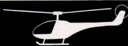
In all kit models, the torque of the tail rotor is counteracted by a tail rotor that pulls in the opposite direction via the lever arm of the tail boom. In calm weather, when hovering is possible with the correct trim and without visible control deflections, you can almost forget about the tail rotor control if the engine is properly tuned. Hovering in one spot becomes even easier when a steady wind is blowing, which stabilizes the helicopter through the wind vane effect of the fuselage side surfaces or the vertical stabilizer.
However, as soon as you want to perform hovering maneuvers, the situation changes. Now cyclic control inputs are necessary to tilt the rotor plane. This requires energy, which can be temporarily drawn from the rotational energy of the main rotor. However, this energy must be replenished, which is achieved by increasing engine power. This, in turn, generates greater torque, which requires a greater tail rotor deflection to prevent rotation about the vertical axis. The increased tail rotor deflection, in turn, results in greater drag, so the engine power must be adjusted once again.
In practice, however, the control process described does not occur in discrete steps but unfolds continuously. This does not change the fact that the pilot must first detect a deviation from the helicopter’s state of equilibrium using his eyes and ears before he can react to it. Due to these slight delays, the tail rotor will be in a state of constant slight instability or, at the very least, will deflect slightly when initiating a different movement of the rotor plane.
By mechanically or electronically applying a fixed amount of tail rotor deflection in conjunction with the pitch and/or throttle servo deflection, it is possible to achieve an approximation of the required corrective deflection. But this is only a first-order approximation.
For this reason, Japanese RC manufacturers developed an electronic unit about four years ago—built into the transmitter and called ATS (Anti-Torque System)—which not only made the magnitude of the additional tail rotor deflection proportional to the throttle servo’s adjustment. In addition, the influence of the rate of change of the throttle adjustment and the duration of the correction could be adjusted using two rotary knobs. Control engineers refer to this as PID control.
Transmitters with such complex features are primarily intended for experts who are also capable of precisely adjusting the three control variables to match their specific helicopter. This requires extensive flying experience. External factors such as gusts of wind or changes in engine performance—for example, due to variations in the elevation of the flying site—cannot be eliminated by this electronic add-on.
Recently, GMP (manufacturer of the CRICKET small helicopter) has also introduced an electronic module compatible with any standard transmitter/receiver in the form of an additional servo box, on which the three parameters—mixing ratio and the influence of the rate of change of the throttle adjustment in terms of magnitude and duration—can be adjusted. This solution is universally applicable and does not require an expensive expert-grade transmitter, because the small servo module is housed inside the helicopter. According to the manufacturer, the device costs only as much as a servo and consumes no additional power.
Electronic speed control systems also respond only to changes in torque resulting from changes in rotational speed (and not to changes in the helicopter’s direction). An inductive or optical sensor on the main rotor shaft detects pulses without contact and adjusts the throttle servo so that the RPM remains constant at a preselected value. This allows tail wobble caused by fluctuating rotor or motor RPM to be compensated for. However, flight maneuvers that require different engine power still necessitate intervention with the tail rotor if the helicopter is not to rotate around the vertical axis. Power is, after all, proportional to the product of torque and rotational speed; therefore, when the rotational speed is kept constant, the torque—and thus the required tail rotor deflection—changes with every change in power. Rotational speed controls are therefore merely a stabilizing aid for the tail rotor. As pure control elements—relative to the entire helicopter—they cannot, by definition, perform attitude control functions.
Such speed control systems were described by Rainer Rebhan in “Flug+modell-technik” 282-7/1979 (“Electronic Speed Controller for Model Helicopters”) and by Dr. A. Kroneisen in “Modell” 12/79 (Speed Controller for Model Helicopters). They are also marketed by the Japanese manufacturer SANWA under the name GOVERNOR, but did not gain widespread use due to the limited assistance they provide to the pilot, as described.
For the average pilot, such electronic aids are of little practical use. Even if an experienced helper sets up the entire system once, it’s only useful until the next crash or until the rotor blades are replaced. After reassembling the rotor head, the adjustment process starts all over again, and due to time constraints, this usually can’t be repeated as often as one might like.
Based on this consideration and taking into account the latest developments in the field of electronics, FUTABA developed a stabilization circuit. The idea of using a mechanical circuit to stabilize a rotational motion is not new. In commercial aviation, Sperry autopilots have been in use for decades. To the best of my knowledge, KAVAN was the first manufacturer of gyros for use in model helicopters. In its day, however, the gyro’s position still had to be detected via a potentiometer. The relatively large hysteresis resulting from the friction of the wiper rendered the system ineffective, especially during the initial subtle course deviations. Consequently, it failed to gain widespread acceptance for design-related reasons.
FUTABA’s solution uses contactless sensing of the gyro’s position via Hall sensors (whatever those may be). What’s important for us is simply that the gyro sends a countersteering command to the tail rotor servo even at the slightest change in its position. This way, any change in attitude is counteracted as soon as even the slightest tendency toward a deviation arises.
However, such a modern gyro system must not be limited to stabilizing the tail rotor. It must be overrideable so that intentional rotations around the vertical axis can be performed. With the FUTABA gyro system—which ROBBE sells under the name “Autopilot” for approximately 240 Swiss francs—the fully wired set consists of the gyro, an electronic unit, and an on/off switch with two adjustment potentiometers ranging from 0...100% for the control input. A switch channel on the transmitter allows you to switch from adjustment range 1 to adjustment range 2 during flight. This is necessary if you want to perform both hovering maneuvers and maneuvers such as turns or approach maneuvers within the same flight program. During hovering maneuvers, manual control of the tail rotor is almost never needed. Therefore, the autopilot’s influence can be set high, e.g., 70–90%. During free flight, you should have more control over the aircraft yourself, so you switch to the other automatic control range, which is, for example, only 30–50%.
The system distributed by ROBBE is powered by the receiver battery. However, since the mechanical gyro consumes quite a bit of power, it is recommended to use a separate 500 mAh rechargeable battery. Connectors for this are included.
There isn’t much to say about the installation itself—the instructions from ROBBE clearly outline all the details.
In England, an RCME gyro kit is available, which allows you to assemble a relatively simple gyro system yourself. For £13, you get the mechanical parts with a balanced flywheel, and for an additional £12, the electronic components with a circuit board, enclosure, and connectors. The fully assembled unit costs £29.84 at World Electronics. That’s (in early 1982) about 110 Fr. The kits are manufactured by Century Systems, 111 Gretton Road, Winchcombe, Cheltenham GL54 5EL, England.
The RCME system consists of a mechanical component and an electronic component, which allows for two settings: servo center position and influence. However, it does not function in the same way as the FUTABA system. Whereas the FUTABA system was a stabilization system, this one merely dampens unwanted rotation around the vertical axis to a greater or lesser extent, while allowing full control inputs to pass through. A description with a diagram can be found in “Radio Control & Electronics,” January 1982.
Finally, the American Watson Stabilizer is worth mentioning. This unit contains no moving parts, consumes less than ¼ watt, and weighs less than 100 g. It does not require its own power source. Its service life is said to be 10,000 hours, and the device is available for $170 (about 320 Fr.) from Watson Industries, Inc., 3041-A Melby Road, Eau Claire, Wisconsin 54701, USA.
The advertisements do not provide a clear description of how this system works. It is described as a “solid-state gyro,” and the inventor writes in the July 1981 issue of “RCM,” p. 94: “The new piezoelectric vibrating beam technology used in our stabilizer will revolutionize the control of model aircraft.” That is all I can say. Perhaps a reader knows more about this new technology and will let me know. I will then try to make the information available to everyone.
In Japan, similar gyro stabilization systems are available on the market in addition to the FUTABA system described above. The SANWA GYROSCOPE SM-340 uses infrared sensing to detect the gyro’s position. I am only familiar with the KO-DIGIACE “SUPER GYRO SG-803” system from advertisements. The same applies to the “GYROSENSOR NEJ 100” from JR-
Propo. This brand is distributed in Western Europe by Graupner, and it’s safe to assume that this gyro will also be available here by the time this article is published. DIGIFLIGHT also offers a gyro system called DIGI GYRO, as does LOGITEC.
With such a wide range of systems that are nearly identical in design and function, it’s likely only a matter of time before these brands appear on our market through the distribution channels of well-known European model retailers. Current price points are likely to be roughly halved, so that the stabilization gyro—with its beneficial effects on flight performance—will soon become standard equipment on a well-equipped, average helicopter. Already today, over 80% of pilots in competitions use these devices. So the hovering maneuvers performed so smoothly don’t always have to be the source of our envy. Besides skill, there’s a good deal of electronics (and money) involved.
Ernst Bernet, Weidstrasse 4a 6300 Zug, Tel. 042 / 21 26 87
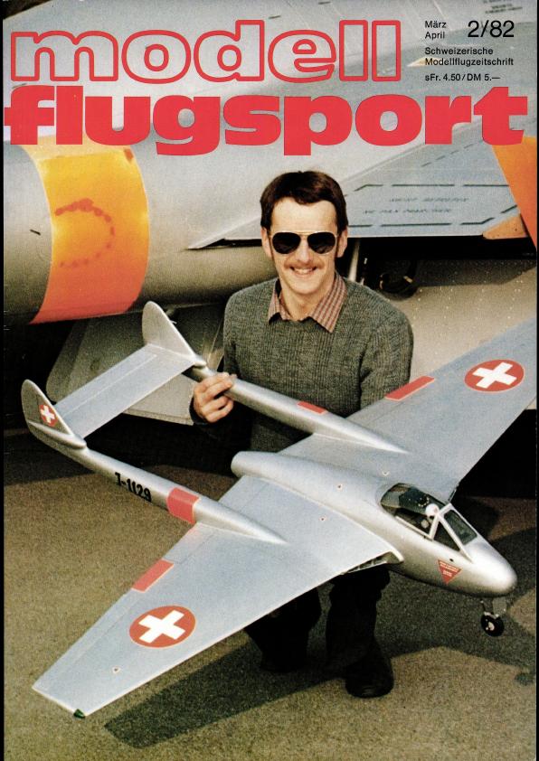

News from HEBU
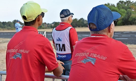
TEAM MANAGER "THIS" BOSSHARD
 Rodito Nussbaumer

YOU KNOW WHAT I MEAN? 125 YEARS OF THE SWISS AERO CLUB
 Emil Giezendanner

SUMMER FUN 2026 AT MG USTER
Martin Wunderli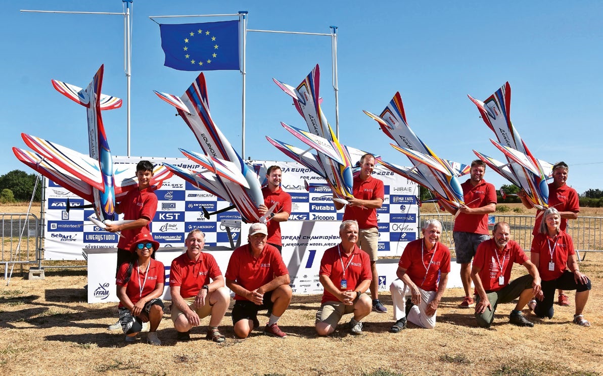
F3A EUROPEAN CHAMPIONSHIPS IN ST-MACAIRE, FRANCE
 Matthias Bosshard
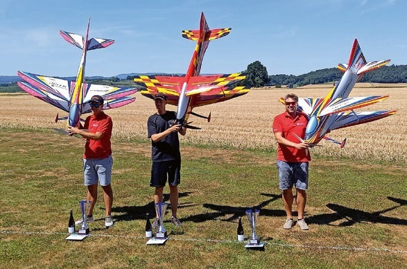
52. 2026 ALPS CUP
Emil Giezendanner
PRIDE AND GOOD IDEAS
 Markus Nussbaumer
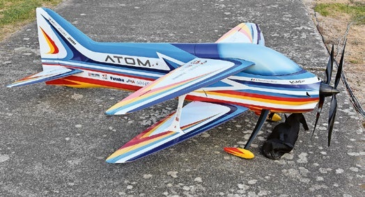
ATOM, THE NEW DOUBLE-DECKER FROM CPLR
Matthias Bosshard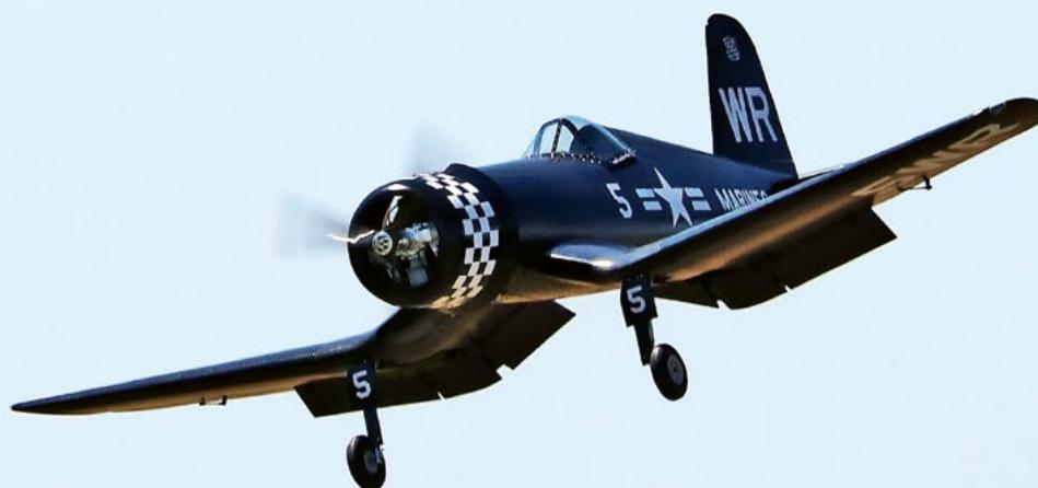
CORSAIR F4U – A WARBIRD WITH A MEMORABLE LOOK
Jürgen Rosenberger, Jürgen Prinz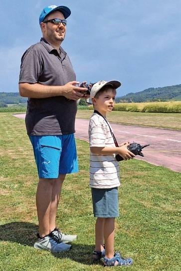
TRY-OUT DAY AT MFV WETTINGEN
Urs Keller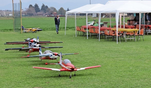
TWIN TOWN PARTNERSHIP
Wolfgang Voeller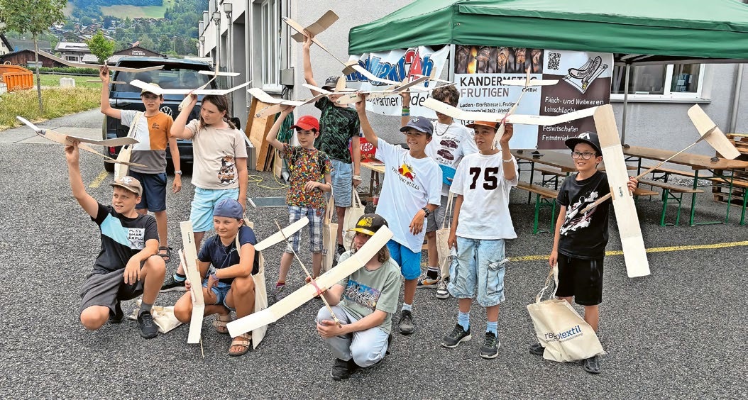
BY YOUTH, FOR YOUTH
Lorena Betschen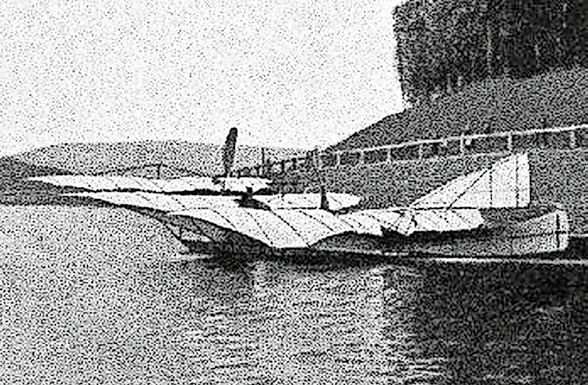
INSIGHTS INTO THE HISTORY OF SEAPLANES
SMALL, MODEL-LIKE SAILBOATS
Res Dauwalder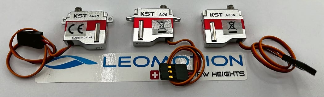
What's New at Leomotion.com
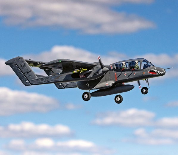
HORIZON HOBBY/LEMACO NEWS: MICRO OV-10 BRONCO 645 MM BY E-FLITE
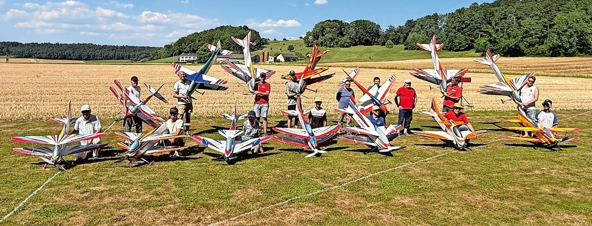
COUPE DES ALPES – OBSERVE AND LEARN
Rodito Nussbaumer
EURO CONTEST GLIDER ACRO TOUR AUSTRIA 2026

34th HAHNENMOOS ALPINE MODEL AIRPLANE CAMP
Res Dauwalder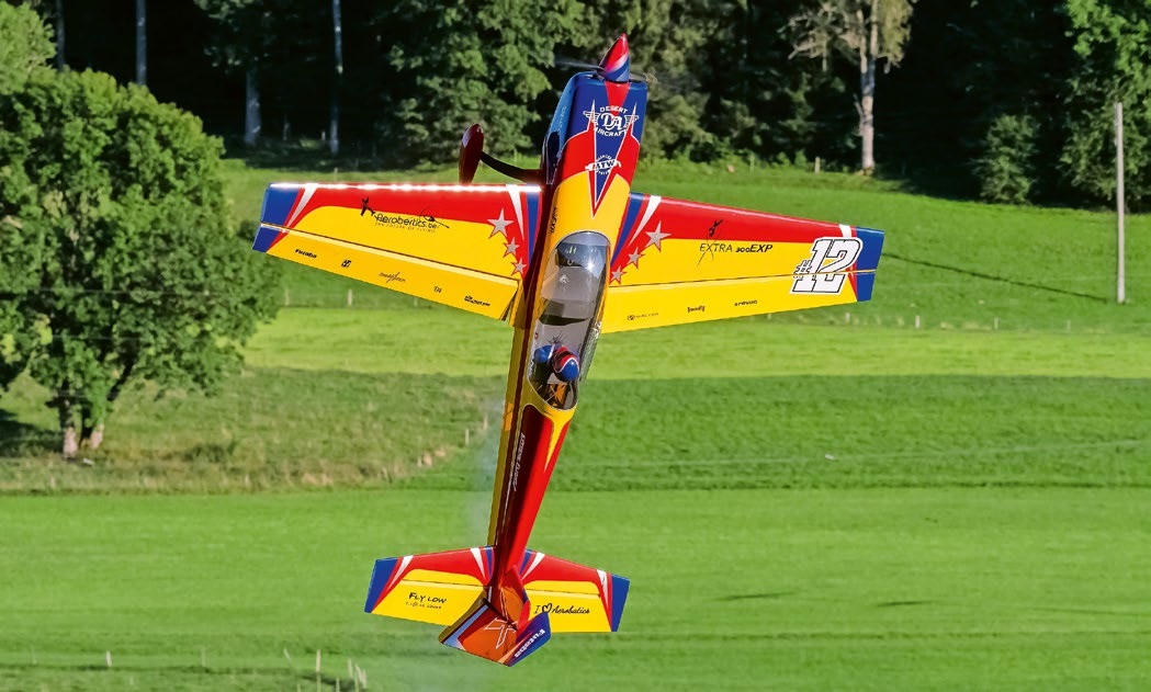
WELCOME, NEW MEMBER!
Andrea Bolliger
FREE FLIGHT IN THE MIDDLE OF SUMMER
Urs Muntwyler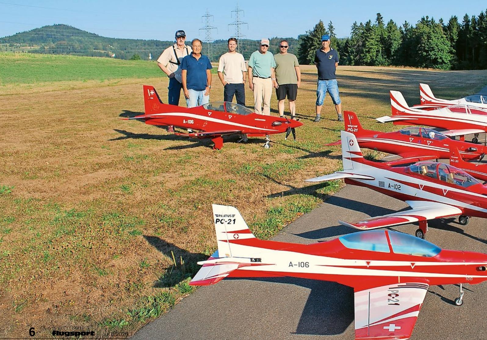
THE PC-21 STORY
Emil Giezendanner
NEWS FROM HEBU
 Julia Bucher
FROM 0 TO 100
Markus Nussbaumer
MEMORIES
Wolfgang Völler
NOS REGION – A HUB FOR ELECTRIC AVIATION
Emil Giezendanner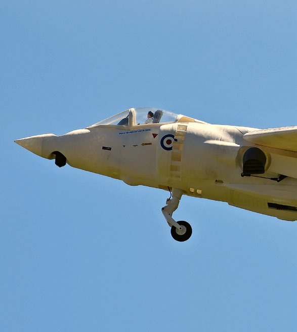
Have you almost forgotten about aircraft that take off and land vertically?
Emil Giezendanner
DO YOU KNOW WHAT I MEAN IN THE LAND OF SMILES?
Emil Giezendanner