
Is the 2.4 GHz Band a Blessing for Model Aircraft?
Is the 2.4 GHz band as secure as pilots would like it to be?
The problem of mutual interference resulting from dual channel occupancy—as was possible on the 35 and 40 MHz bands—is eliminated thanks to the transmission procedure used on the 2.4 GHz band. Such protocols have long been proven in the industry. The telemetry capability (as offered in the latest generation of remote controls) provides additional assurance regarding the range of the radio link, as the pilot is alerted when the signal becomes too weak. The transmission response time is significantly shorter than before, thanks to the “Servopulse” pulse-width modulation.
Temporary signal errors are identified through the digital encryption of control commands in the receiver and then corrected or eliminated to prevent any malfunctions. Third-party transmitters are recognized by the receiver and ignored.
Microwave signals behave almost like light. Therefore, you can only fly “within sight.” If, intentionally or not, the remote-controlled model flies behind buildings, hills, or other obstacles, the strength of the radio signals is greatly reduced and may even drop to zero (though reflections can sometimes help). The 2.4 GHz band is a so-called “ISM” band. We must share this frequency band (which we fully utilize with frequency-hopping spread spectrum) with other services in industry, science, and medicine. This means for us
that, in principle, the transmission channel may be occupied by other users. Frequency bands can be disrupted by interfering signals (for example, from leaky microwave ovens, up to 1 kilowatt). Powerful commercial transmitters, which do not operate in the ISM band, can also interfere with remote control receivers due to strong electromagnetic fields. This applies in principle to all radio transmissions.
- Faults in the transmitter or receiver itself, or user errors.
- Third-party users on the 2.4 GHz ISM band.
- Presence of strong electromagnetic fields.
- Interference from various frequencies in the receiver.
Any potential interference with the remote control's radio signal must be taken seriously, as it could cause our model to crash.
The front part of the receiving antennas is their active section. The gray or black part is the shielding (coaxial cable), from which the antenna is made. The inner conductor (which we can see for about 3 cm) consists of 7 thin wires, each only 0.06 mm thick (roughly the thickness of a strand of hair). Multiple bends
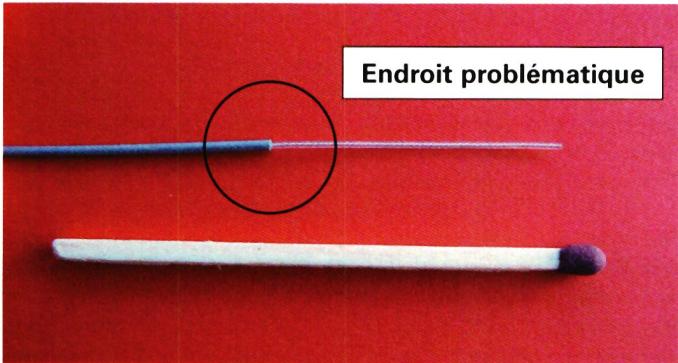
can cause hard-to-see wire breaks inside the polyethylene sheath. In this case, the antenna will no longer receive a signal, and of two antennas, only one would still be active. This could result in “dead spots” in reception. Inside the receiver, the cable is connected via a miniature connector. These connectors have only limited resistance to cable tension. If the antenna cable is pulled too hard, they can become disconnected from the contact point without being visible to the naked eye. To avoid any risk of signal attenuation, the antennas should protrude from the model’s fuselage. Carbon fiber, metal, and certain colored pigments absorb high-frequency signals. Fiberglass epoxy, however, allows high frequencies to pass through.
For optimal reception quality, follow the manufacturers’ recommendations: position the two antennas at a 90° angle and as far apart from
each other. It’s not just a matter of degree; two antennas oriented parallel to each other will fail to function properly. The “fail-safe” should be engaged on fixed-wing models, with the engine idling in all cases, for safety reasons.
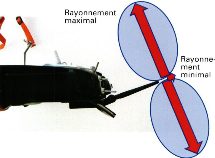
All rod antennas are Hertzian dipoles, with radiation emitted radially at a 90° angle to the rod's axis. Propagation is minimal along the axis of the rod, which can reduce the range by several orders of magnitude. This also explains why the two receiving antennas must be positioned at a 90° angle to each other. Therefore, the transmitting whip antenna should never point toward the model (modules without a visible antenna use a patch antenna, which has different radiation characteristics).
Who doesn’t carry a cell phone in their jacket these days, even while flying model airplanes? Since many flying fields are located away from urban areas, cell phone reception there is often very weak. In an effort to maintain its connection (even when no calls are being made), the cell phone sends out brief but very powerful signals every few minutes. Depending on the circumstances, these signals can interfere with our transmitters.
Bluetooth and Wi-Fi systems use the same frequency band as our 2.4 GHz devices, and Wi-Fi networks are also more powerful. If there are many Wi-Fi networks operating simultaneously (as may be the case in an industrial environment), they can completely monopolize the available transmission band and interfere with our radio link to our model. The greater the distance between us and the receiver, and the closer the receiver is to the third-party transmitter, the greater the risk of interference. Such third-party devices should be turned off at the flight site to avoid the risk of interference (even if such interfering signals do not interfere with frequency-hopping spread spectrum). In our own best interest, we should not push our luck too far.
Presence of strong electromagnetic fields.
Very high-power third-party transmitters can interfere with our receivers, since they generate strong electromagnetic radiation. Broadcast transmitters
operate at frequencies below 1 GHz, but at power levels ranging from 10 watts to over 100 kilowatts. If our model comes into close proximity to such transmitters, the receiver’s input stage may become saturated, preventing the remote control signal from being received or decoded.
Cell phone antenna installations also have a range of transmission powers, varying from 10 to over 1,000 watts, with frequencies between 900 and 2,200 MHz. The same effect can occur.
Mixed signals resulting from multiple transmitted signals may form at the receiver's input and may then fall within the ISM band.
However, at two model airplane fields that had experienced interference, no interfering signals at 2.4 GHz could be detected. Nevertheless, cell phone towers and broadcast facilities were located nearby. A spectral analysis identified which signals, and at what field strength, were present at the time of measurement.
The measured signals were reproduced individually in the laboratory, but no interference was observed on the receiver. The receiver only triggered its “fail-safe” mode upon simultaneous reception of two third-party signals.
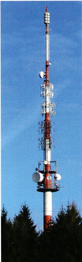
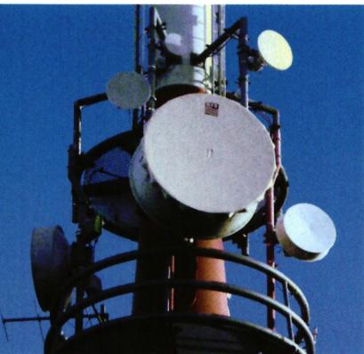
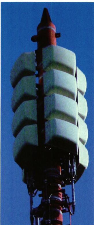
There are two main types of transmission towers.
The Federal Office of Communications (OFCOM) makes maps and data available online for public review.
•
The locations of the transmitting facilities and their characteristics are shown on the map. For each facility, there is a table listing the services provided and their radiated power.
To ensure uninterrupted reception of our signal, the distance from the transmitting stations should be as great as possible.
- Distance to a digital TV transmitter, such as Rigi Kulm (112 kW), at the height of the antenna: > 8 km
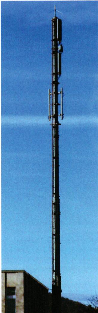
- Distance to the repeater (10 kW): > 2 km
- Distance to GSM facilities (1 kW): > 500 m
This does not mean that you should not fly within these distances, but it is nonetheless advisable to identify any potential interference as early as possible and to fly out of the danger zone.
Interference signals outside the 2.4 GHz band can be suppressed using appropriate filters. One such filter, which was specifically developed for the 2.4 GHz band, measures 5 × 3 × 1.5 mm.
and can be integrated into the antenna line without causing significant signal loss. It has been implemented by manufacturers of 2.4 GHz receivers.
For an analysis, it is essential to know:
- the time of the disturbance (as precisely as possible);
- the direction, distance, and altitude at which the disturbance occurred;
- which transmitters and receivers were in use at that time.
For a flying field where interference occurs, it is advisable to keep a log containing all the information mentioned above. This will help identify the problems more effectively.
Targeted measurements using a spectrum analyzer can provide insight into the high-frequency conditions prevailing at the flying field.
Assistance can be requested from the FSAM Infrastructure Department.
The new remote control technology for 2.4 GHz models is now well established, and you can rely on it without
reserves. However, we must be aware that every technology, no matter how good it may be, also has its limits, which cannot be crossed without consequences. Anyone who exceeds
exposes themselves to increased risks. But anyone who understands these limits will be committed to staying within them.
*FSAM Infrastructure Division, Paul Rudolf*


News from HEBU

HORIZON HOBBY/LEMACO NEWS: MICRO OV-10 BRONCO 645 MM BY E-FLITE

PRIDE AND GOOD IDEAS
 Markus Nussbaumer

TEAM MANAGER "THIS" BOSSHARD
 Rodito Nussbaumer

YOU KNOW WHAT I MEAN? 125 YEARS OF THE SWISS AERO CLUB
 Emil Giezendanner

F3A EUROPEAN CHAMPIONSHIPS IN ST-MACAIRE, FRANCE
 Matthias Bosshard

ATOM, THE NEW DOUBLE-DECKER FROM CPLR
Matthias Bosshard
SUMMER FUN 2026 AT MG USTER
Martin Wunderli
What's New at Leomotion.com

52. 2026 ALPS CUP
Emil Giezendanner
TWIN TOWN PARTNERSHIP
Wolfgang Voeller
34th HAHNENMOOS ALPINE MODEL AIRPLANE CAMP
Res Dauwalder
CORSAIR F4U – A WARBIRD WITH A MEMORABLE LOOK
Jürgen Rosenberger, Jürgen Prinz
SMALL, MODEL-LIKE SAILBOATS
Res Dauwalder
TRY-OUT DAY AT MFV WETTINGEN
Urs Keller
WELCOME, NEW MEMBER!
Andrea Bolliger
FREE FLIGHT IN THE MIDDLE OF SUMMER
Urs Muntwyler
COUPE DES ALPES – OBSERVE AND LEARN
Rodito Nussbaumer
EURO CONTEST GLIDER ACRO TOUR AUSTRIA 2026

BY YOUTH, FOR YOUTH
Lorena Betschen
INSIGHTS INTO THE HISTORY OF SEAPLANES

THE PC-21 STORY
Emil Giezendanner
NEWS FROM HEBU
 Julia Bucher

FROM 0 TO 100
Markus Nussbaumer
MEMORIES
Wolfgang Völler
NOS REGION – A HUB FOR ELECTRIC AVIATION
Emil Giezendanner
DO YOU KNOW WHAT I MEAN IN THE LAND OF SMILES?
Emil Giezendanner
Have you almost forgotten about aircraft that take off and land vertically?
Emil Giezendanner