
Fast Charging and Maintenance of NiCd Sintered Cells for Electric Drives
From the wide variety of cells available, we will focus only on those currently in most common use. Cells used in electric model drives must meet the following requirements:
1. gas-tight
2. orientation-independent
3. fast-charging
4. low internal resistance
5. lightweight (for model airplanes)
6. inexpensive
7. as durable and low-maintenance as possible
Cells with these properties are currently offered by several companies (VARTA, General Electric, SAFT, Sanyo, Daimon, and others) under various brand names in capacities of 0.5 Ah, 0.75 Ah, 1.2 Ah, and 1.8 Ah. The 1.2-Ah cell is currently the most widely used. All of the following considerations therefore refer to this cell. However, with the appropriate conversion factors, the same applies to the other cells as well.
To help you better understand the following, here is a list of the most common terms and abbreviations used when working with NiCd cells:
1. Voltage U, measured in volts (V) or millivolts (mV)
2. Current I, measured in amperes (A) or milliamps (mA)
3. Resistance R, measured in ohms (Ω) or milliohms (mΩ)
4. Power P, measured in watts (W) or milliwatts (mW)
5. Cell capacity, measured in ampere-hours (Ah) or milliampere-hours (mAh)
These quantities are related to one another by the following equations:
1. Ohm’s Law: U = I · R
2. Power Law: P = U · I
3. The rated capacity of a fully charged cell is the amount of current that can be drawn over a specified discharge time. Internationally, the discharge time for fast-charge-capable cells has been set at one hour. In Europe, a discharge time of five hours is used for fast-charge-capable cells and ten hours for non-fast-charge-capable cells.
4. The charge and discharge rate is the current that flows during a specific period of time while charging or discharging. Due to the different definitions of rated capacity, a distinction is made between the C-rate (international) and the I5 and I10 rates. The C-rate is the current value in amperes during one hour of charging or discharging and is numerically equal to the cell’s rated capacity in Ah, i.e., the C-rate of a cell with a 1.2-Ah rated capacity is 1.2 A. This current can be drawn from a fully charged 1.2-Ah cell for one hour.
The I5 rate of a cell with a nominal capacity of 1.2 Ah corresponds to a current of 0.24 A = 240 mA (= 1.2 A ÷ 5). This current can be drawn from a fully charged cell for five hours.
The I10 rate of a 1.2-Ah cell corresponds to a current of 0.12 A = 120 mA (1.2 A ÷ 10). This current can be drawn from this cell for ten hours. The various charge and discharge rates are related by the following ratios:
1 C-rate = 5.0 × I5 rate = 10 × I10 rate
, or alternatively
, I10 = 0.1 C = 0.2 × I5 and I5 = 0.2 C = 2 × I10
Due to efficiency, all charging times are about 40% longer than discharging times. There are three types of charging:
Charge at a rate of 0.2–0.3 C or 2 · I10 – 3 · I10. The cell can generally withstand these charging currents continuously, so the charging time does not need to be strictly limited; for example, charging an RSH 1.2 at 0.2 C for seven or more hours is a standard charge.
For charging currents exceeding 0.3 C, the charging time must be limited in accordance with the charging current. It is necessary to monitor accelerated charging using a timer. A charge rate of 0.5 C corresponds to a charging current of 0.6 A. The charging time in hours is then equal to (1.4 : charge rate in C), i.e., in this case, 1.4 : 0.5 = 2.8 hours.
Fast charging generally refers to charging times of less than one hour. The most common method is the half-hour charge. In this process, the cell (battery) is discharged down to 0.9–1.0 V per cell. Rapid charging then takes place via a suitable resistive cable for half an hour at 2 C. For a 1.2-Ah cell, this means a charging current of 2.4 A, which is drawn from a suitable power source, usually a vehicle battery. Charging must be stopped exactly after half an hour; otherwise, there is a risk of permanent damage to the cells. Automatic chargers are now available that spare the hobbyist the trouble of pre-discharging and timing the process.
After 5 to 10 rapid charges of a battery, a normal charge at 0.2 to 0.3 C—lasting about five to seven hours—should be performed. Before using the battery, recharge it at 2 C for two to five minutes.
If more than half an hour elapses between fast charging and use, recharge for another two to four minutes at 2 C; follow the same procedure for batteries that are fast-charged automatically.
Deeply discharged batteries must be recharged immediately! If they are not going to be used right away, charging them for just a few minutes is enough to restore the cells to their normal voltage.
Do not recharge hot batteries immediately; let them cool down to body temperature first!
For smooth charging, all cells in the battery must be of equal capacity. Do not connect cells from different manufacturers together! Do not fast-charge charged and uncharged cells together.
Fault
1. A single cell is overheating:
2. Battery does not accept a charge:
3. Battery charges but does not maintain voltage under load:
Cause or Solution
: Defective cell! Replace it.
Break in the wiring, poor connector connection, or similar issue. Check individual cells! Check the wiring!
Connect empty cells or an empty battery to a fast-charging device and immediately measure the voltage of each individual cell. Good cells will have a voltage of approximately 1.2–1.4 V at the start of fast charging. If the display shows 1.6 V or more, the cell is no longer suitable for high-current operation! This test should be repeated from time to time.
In almost all cases, the capacity of the built-in battery is large enough to charge the model’s onboard battery five to ten times without any difficulty, provided the car battery is in good condition. It is recommended to maintain the car battery on a regular basis to avoid any unpleasant surprises.
The vehicle battery should have a voltage of approximately 12.5 to 13 V when unloaded; the voltage must not drop below 12 V when loaded by a quick charger, otherwise the vehicle’s ability to start would be compromised. Your automotive electrician will adjust your car’s regulator to the optimal setting; this takes just a few minutes and saves you hours of hassle when the battery is dead.
Let’s first consider the load capacity of an RSH 1.2 NiCd sintered cell. Data sheet 1 shows that these cells can be loaded as follows:
| Time in minutes | Load current in A | Usable capacity in Ah |
| 60 | 1.2 | 1.2 |
| 20 | 3.0 | 1.0 |
| 9 | 6.0 | 0.9 |
| 3.7 | 12.0 | 0.75 |
| 1.7 | 24.0 | 0.68 |
From these randomly selected values, it is clear that the capacity decreases as the current increases; that is, the higher the current load, the shorter the relative operating time.
If we further examine the voltage of the cell at the currents listed above (Curve Sheet 2), we see that the usable voltage also decreases as the load increases.
Finally, from graph sheet 3, we can determine the cell’s voltage as a function of temperature. As the temperature rises, the voltage decreases, on average by -4 mV/°C.
These are the most important characteristics of a cell. From these, the possible operating parameters can now be derived.
The current that a cell can deliver is theoretically limited only by its internal resistance. This means that short-circuiting a charged cell or battery can have serious consequences. In practice, however, such high currents should be avoided at all costs, because the cell heats up very quickly, which leads to poor voltage performance and capacity yield, and at temperatures above 60°C can even result in destruction.
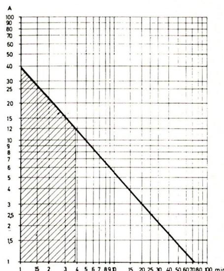
As shown in Curve Sheet 1, currents of up to 12 A can be drawn continuously until the cell is discharged. For higher currents, operation is only possible in intervals due to heating.
We now know that the current draw from a cell can only be increased at the expense of usable capacity. Those who do not wish to accept this must increase the voltage to boost performance, i.e., use more cells per battery pack.
Let’s assume that an electric drive is supposed to operate for nine minutes and that an electrical power (battery power) of 120 W is available.
From Chart 1, we can see that the average current can then be 6 A. The usable (dischargeable) capacity is 0.9 Ah. For a current of 6 A and an available power of 120 W, we need a voltage of 120 : 6 = 20 V. From Curve Sheet 2, we see that the voltage of a single cell at 6 A is 1.17 volts.
This results in a number of cells of 20 ÷ 1.17 = 17 cells.
A motor is available that requires an input power of 150 W at a motor voltage of 10 V. How many cells are needed, and how long will the motor run with these cells? The required motor current is calculated from the power and motor voltage: 150 W : 10 V = 15 A. Table 1 shows a runtime of approximately 3.2 minutes. Since this time is already outside the continuous operation range, uninterrupted operation is not permitted.
From Curve Sheet 2, we see that for a load current of 15 A, the cell voltage is 1.05 volts. To achieve a motor voltage of 10 V, we therefore need 10 : 1.05 = 10 cells.
Finally, it should be noted that there are a few prerequisites for working with electric motors. Just as an internal combustion engine requires a starter battery and a fuel system, electric motors require a voltmeter. It should have a range of 3–5 V as well as additional ranges up to approximately 30 V. Furthermore, it should have a resistance range for continuity tests and the ability to measure rotational speeds. To complete the setup, you will also need a stopwatch.
Current measurements are best taken indirectly using the stopwatch and Chart 1.
Caution: Be careful with no-load measurements! Well-tuned drives cannot tolerate no-load operation, as the current draw is much higher than during normal operation.
Anyone who is unfamiliar with the most basic principles of electrical engineering or is unwilling to learn them should be advised against working with electric drives. All other model builders are sure to enjoy their new-generation electric drive and will soon discover that, despite its disadvantages compared to the internal combustion engine, the electric drive has several significant advantages, such as no backfiring problems and no dirty models; the electric drive can be turned off and on at any time, there are no vibrations, no odor, and it makes only minimal noise. However, it would be wrong to believe that the electric drive could replace the internal combustion engine in the foreseeable future. Nevertheless, the electric drive has earned its place in model building and will retain it.
The new technologies currently under development will reduce the power-to-weight ratio of rechargeable cells. It is still too early to say whether and when this will have an impact on us. The automotive industry is currently making tremendous efforts to advance electric vehicles. If these efforts are successful, the model-making industry will benefit as well.


News from HEBU

HORIZON HOBBY/LEMACO NEWS: MICRO OV-10 BRONCO 645 MM BY E-FLITE

PRIDE AND GOOD IDEAS
 Markus Nussbaumer

TEAM MANAGER "THIS" BOSSHARD
 Rodito Nussbaumer

YOU KNOW WHAT I MEAN? 125 YEARS OF THE SWISS AERO CLUB
 Emil Giezendanner

F3A EUROPEAN CHAMPIONSHIPS IN ST-MACAIRE, FRANCE
 Matthias Bosshard

ATOM, THE NEW DOUBLE-DECKER FROM CPLR
Matthias Bosshard
SUMMER FUN 2026 AT MG USTER
Martin Wunderli
What's New at Leomotion.com

52. 2026 ALPS CUP
Emil Giezendanner
TWIN TOWN PARTNERSHIP
Wolfgang Voeller
34th HAHNENMOOS ALPINE MODEL AIRPLANE CAMP
Res Dauwalder
CORSAIR F4U – A WARBIRD WITH A MEMORABLE LOOK
Jürgen Rosenberger, Jürgen Prinz
SMALL, MODEL-LIKE SAILBOATS
Res Dauwalder
TRY-OUT DAY AT MFV WETTINGEN
Urs Keller
WELCOME, NEW MEMBER!
Andrea Bolliger
FREE FLIGHT IN THE MIDDLE OF SUMMER
Urs Muntwyler
COUPE DES ALPES – OBSERVE AND LEARN
Rodito Nussbaumer
EURO CONTEST GLIDER ACRO TOUR AUSTRIA 2026

BY YOUTH, FOR YOUTH
Lorena Betschen
INSIGHTS INTO THE HISTORY OF SEAPLANES

THE PC-21 STORY
Emil Giezendanner
NEWS FROM HEBU
 Julia Bucher

FROM 0 TO 100
Markus Nussbaumer
MEMORIES
Wolfgang Völler
NOS REGION – A HUB FOR ELECTRIC AVIATION
Emil Giezendanner
DO YOU KNOW WHAT I MEAN IN THE LAND OF SMILES?
Emil Giezendanner
Have you almost forgotten about aircraft that take off and land vertically?
Emil Giezendanner