
A little rustic—but not too much
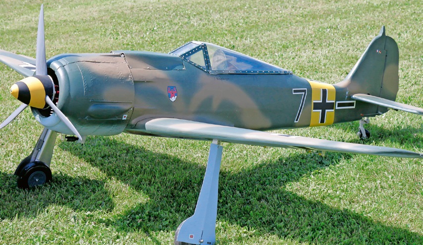
Focke Wulf 190 A8 from Fokke RC
While browsing the Internet, I came across the website of Fokke RC Bulgaria, a company that has “almost” revived the traditional method of manufacturing wooden model kits and offers a wide selection of World War II classics: Me 109, Focke-Wulf, Spitfire, MiG, etc.
Interestingly, models are available in various scales ranging from 1:5, 1:4, and 1:3, all the way up to—oh my—1:2. I quickly got in touch with Rumen Charakov, the company’s CEO, placed an order; six weeks later, a Focke Wulf A8 model kit in the
1:5 scale. The kit includes a 1:1 construction plan, ribs, and frames made of laser-cut poplar plywood, as well as the engine cowling and canopy; it lacks battens, covering material, and any accessories such as linkages, wheels, etc. There are no written instructions. Charakov responds to email inquiries every minute, which turns out to be very helpful as the build progresses.
In the first step, we fold the laser-cut side panels; they then enclose the cabin space, after which we connect them to each other at the front and rear using a frame. The rounded contour
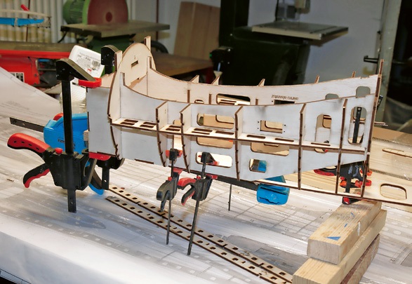
The fuselage is constructed using half-frames that are slotted into place on the sides using the tongue-and-groove principle. The next step in the build must be planned carefully—it involves attaching the tail section. On both sides, as well as at the top and bottom, place a pre-cut, grooved
and fit the frames in one by one. I aligned all the frames—each fitted with small feet—along a straight line on the workbench to secure them in place. When inserting the pine strips, one shortcoming was that the notches for
The stringers need to be filed down. Nevertheless, within a reasonably short time, a sturdy hull frame is created from milled frames and deck plates, stabilized by battens. After removing the hull from the slipway and checking the longitudinal axis with a laser, it becomes clear: The hull is warped lengthwise! With my hands almost numb, I grab the saw and cut through
the stringers on one side. On the top surface—at the front, in the center of the hull, and at the rear—the centerline is marked with pins, aligned using the laser beam, and re-glued over pieces of stringer placed underneath. The next step is to skin the fuselage with 2.5-mm balsa wood, which proves to be quite challenging due to the curves. On top of that, given
gritting my teeth, I’ll decide to cover the fuselage, wings, and tail surfaces with 49 g/m² mat due to the high vulnerability of the balsa outer skin.
The included engine cowling is made of fiberglass—let’s call it—rustic construction; the weathering effect so beloved by perfectionists is already anticipated here.
The elevator’s damping surface is permanently glued in place; the control surfaces are actuated—with the exception of the
rudder—via servos mounted on the airframe. The 1:1 construction plan shows a straight engine installation (angle 0°/0°); Rumen does not comment on this upon request, so I’m choosing the usual 2.5° down and 2° to the right—further adjustments will be determined during flight testing.
Let's turn our attention to wing construction. The ribs are made entirely of 3-mm plywood—a nod to the
| Wingspan: | 2100 mm |
| Length: | 1,800 mm |
| Weight: | 12.0 kg |
| Center of gravity: | 140–150 mm behind the nose strip |
| Engine: | DLA 56 + TC pot damper |
| Propeller: | Elster 2-blade propeller 22/10 |
| Servo setup: | 5× Turningy 629HS; ailerons, landing flaps, rudder |
| Elevator: | 2× KST 215 mg |
| Battery switch: | DPSI RV |
Weight gain. The individual ribs are positioned on the template using small feet; if the grooves fit well, the ribs are assembled in sequence using a jaw strip, a comb rail, and another jaw strip. The cutouts for installing the tube-fitting system—which is not included in the kit—are precisely sized, so no reworking is necessary. The four flaps are glued together from two pre-milled blanks each and stabilized over a strip. The landing flaps, as well as the ailerons, are to be mounted gap-free using small balsa blocks and notches in the control surfaces.
The canopy is the Focke-Wulf’s defining feature. The structure intended by the designer—consisting solely of a 3-mm beech plywood
does not provide a stable framework. My modification: The windshields are placed as a single unit over the front cockpit frame, with 2-mm aluminum strips positioned above them and screwed onto the wood. The rear, sliding cockpit consists of a large transparent canopy, a plywood support plate, and a bullet trap formed from balsa strips. We designed the sliding mechanism as a central wooden rail beneath the canopy panel that slides in a groove in the airframe.
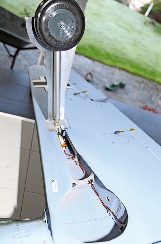
The Focke-Wulf has a wide-set, long-legged landing gear. Long struts generate high torsional forces at the wing root during landing—which means a GFK-Stabili-
bearing is recommended. Furthermore, I’d had a bad experience with steel spring dampers on a JU 87—every landing turned into a hard-to-control “bouncing goat” event! I have custom gas-pressure dampers made by Wolfgang Liening/Modellbaustudio; an Electron landing gear—not exactly cheap, but trouble-free to use—is also included. As for the paint scheme, the lower part of the aircraft is painted the usual sky blue, while the upper part features a green-brown camouflage scheme; however, I deliberately avoid specifying a particular fighter wing—to steer clear of any glorification.
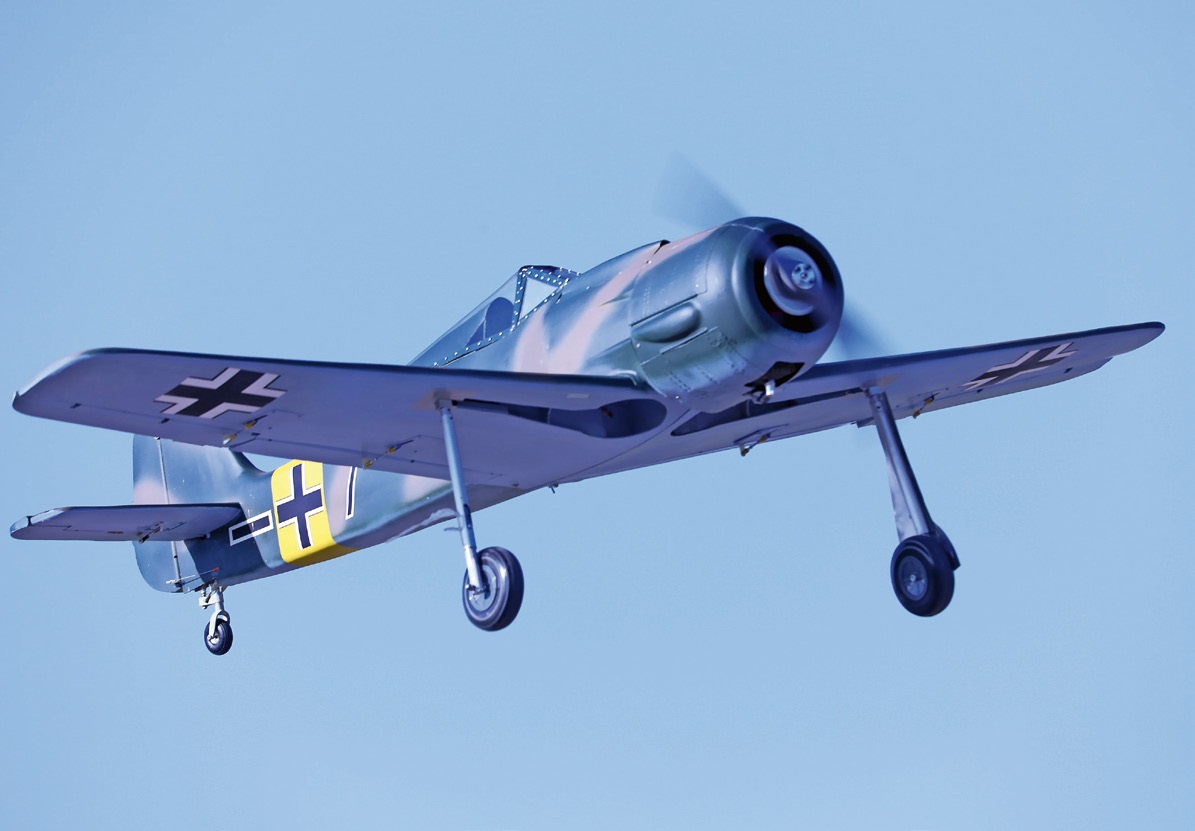
The pictures show the Spinner’s lovingly painted snail-shaped plane with a 21/12 three-bladed Elster propeller. The plane taxis up, takes off, turns left, lifts its nose slightly, the engine cuts out, and it touches down. Thank goodness the grass outside the runway is several meters high; the damage from the crash landing is thus limited. The landing gear, which hadn’t been retracted yet, is torn off, one propeller blade is broken, and the engine cowling has a crack. Attempt at a failure analysis—the DLA 56 cannot handle a 21/12 three-bladed propeller; later tests with a 22/10 two-bladed propeller are successful. Second point: The center of gravity, which was well balanced in the front third of the model in my basement
—probably needs to be adjusted, as the flight was too short. The detached landing gear is repositioned, and paint damage is repaired. I shift the center of gravity 1 cm forward; as a result, an additional 500 g of lead must be placed in the cowl. The DLA 56 I used weighs 1,290 g. With a ZG 62 weighing 2,040 g, we probably wouldn’t have needed any ballast.
Another point of criticism: The manufacturer specifies the use of 3-mm plywood for the entire airframe—including the tail—along with a scale tailwheel, two servos in the elevator, and the paint job. Bottom line: Tail-heavy handling is inevitable. Next attempt—takeoff after about 50–60 m. Our fears following the failed maiden flight—that this was an unflyable aircraft—are not confirmed. Once this by no means lightweight model has picked up speed, control inputs are executed swiftly: roll left, roll right as if pulled by a string; inverted flight is no problem. The motorization is adequate and, within limits, suitable for aerobatics. The photos show that when the right Electron landing gear retracted, the aluminum cover fell off; the leg somehow twisted. Overall—
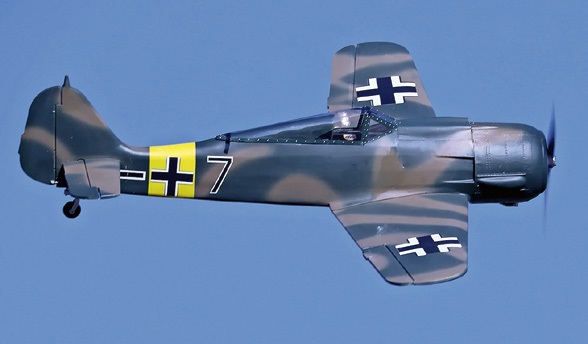
along with—as the images show—an impressive flight performance.
A challenging project for woodworking enthusiasts. An airframe constructed entirely from 3-mm plywood could have its weight minimized—for example, in the wing area—by incorporating balsa wood. Despite its considerable wing loading, the 1/5-scale FW 190 A8 has good flight characteristics; it responds to control inputs smoothly and harmoniously. Fokke RC offers the D8, a long-nose version in the same scale, which should make center-of-gravity balancing easier. A happy outcome is worth waiting for!


News from HEBU

TEAM MANAGER "THIS" BOSSHARD
 Rodito Nussbaumer

YOU KNOW WHAT I MEAN? 125 YEARS OF THE SWISS AERO CLUB
 Emil Giezendanner

F3A EUROPEAN CHAMPIONSHIPS IN ST-MACAIRE, FRANCE
 Matthias Bosshard

SUMMER FUN 2026 AT MG USTER
Martin Wunderli
TRY-OUT DAY AT MFV WETTINGEN
Urs Keller
52. 2026 ALPS CUP
Emil Giezendanner
BY YOUTH, FOR YOUTH
Lorena Betschen
ATOM, THE NEW DOUBLE-DECKER FROM CPLR
Matthias Bosshard
CORSAIR F4U – A WARBIRD WITH A MEMORABLE LOOK
Jürgen Rosenberger, Jürgen Prinz
SMALL, MODEL-LIKE SAILBOATS
Res Dauwalder
What's New at Leomotion.com

HORIZON HOBBY/LEMACO NEWS: MICRO OV-10 BRONCO 645 MM BY E-FLITE

TWIN TOWN PARTNERSHIP
Wolfgang Voeller
PRIDE AND GOOD IDEAS
 Markus Nussbaumer

EURO CONTEST GLIDER ACRO TOUR AUSTRIA 2026

INSIGHTS INTO THE HISTORY OF SEAPLANES

34th HAHNENMOOS ALPINE MODEL AIRPLANE CAMP
Res Dauwalder
WELCOME, NEW MEMBER!
Andrea Bolliger
FREE FLIGHT IN THE MIDDLE OF SUMMER
Urs Muntwyler
COUPE DES ALPES – OBSERVE AND LEARN
Rodito Nussbaumer
THE PC-21 STORY
Emil Giezendanner
NEWS FROM HEBU
 Julia Bucher

FROM 0 TO 100
Markus Nussbaumer
MEMORIES
Wolfgang Völler
NOS REGION – A HUB FOR ELECTRIC AVIATION
Emil Giezendanner
Have you almost forgotten about aircraft that take off and land vertically?
Emil Giezendanner
DO YOU KNOW WHAT I MEAN IN THE LAND OF SMILES?
Emil Giezendanner