
Measuring Electrical Currents Correctly in the Receiving System: Workshop 2
In the last workshop, we familiarized you with the basic use of the digital multimeter (DMM). As the first important quantity measured in electrical systems, you learned about electrical voltage, which is measured in volts. Through a few hands-on exercises, we built a bridge to our model aircraft hobby. We hope you understood everything, so we can now quickly move on to discussing another important quantity—electric current, measured in amperes—and understand its significance for our avionics through a few more lab exercises. For this, you’ll need our DMM again and a special cable, which is very easy to make.
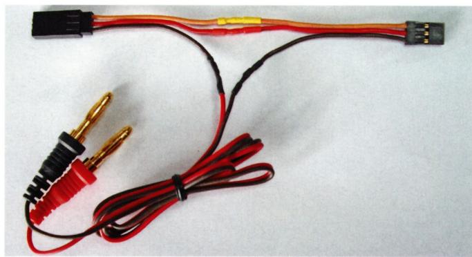
Build an adapter cable as shown in Figure 1. To do this, you’ll need a servo extension cable and, for simplicity’s sake, a battery charger cable with a banana plug on one end. We now have an adapter cable that can be connected to a circuit via the DMM using the banana plugs.
The key difference from voltage measurement becomes apparent here. Voltage is measured directly at the terminals of the device under test. To measure current, however, you must interrupt the circuit at some point and connect the DMM. By connecting the DMM in this way and selecting the correct current measurement range on the DMM, the circuit is correctly closed again within the DMM. It is important that the selected measurement range is reasonably proportionate to the expected current value. We will point this out in each of the following lab exercises.
In this exercise, we are interested in the power consumption of a typical receiver system consisting of a receiver and a servo. As shown in Figure 2, our adapter cable is connected immediately after the power supply battery. This means that the current also flows through the DMM, which is connected via the banana plugs, and can thus be measured. An important prerequisite for an accurate current measurement is that the result is not distorted by the measuring instrument connected in the circuit. It must not
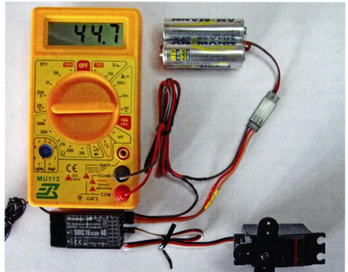
No energy—or at most only a negligible amount—is diverted for the measurement. The DMM does exactly that when one of the current ranges is selected. Its internal resistance is approximately zero, as in a short circuit. The higher the selected current range, the smaller and more negligible the internal resistance. If you accidentally set the DMM to a voltage range, you will notice that your connected receiving equipment or load does not operate, since the DMM has switched to the highest possible internal resistance. Anyone interested in learning more about the inner workings of a typical modern DMM can find additional information on our blog (blog.innoflyer.ch) under the topic “Inside DMM.”
Important note: NEVER take a voltage measurement in a current range on the DMM that was selected by mistake! This will cause a SHORT CIRCUIT in the power supply, with all the possible undesirable consequences. Typically, the current ranges on the DMM are
protected by a fuse, but a short circuit can always lead to unexpected secondary damage
Select the 200 mA measurement range. Turn on the power supply. Measure the system’s quiescent current. This should be around 50 mA. But in reality, our models will be anything but at rest. Move the servos using the transmitter’s joystick or gently by hand on the servo arm (be careful not to overload the gears!). You’ll notice a significant change in current depending on the load. This demonstrates why understanding currents in electrical systems is so important. Switch to a higher measurement range—typically the 10-A range on simple DMMs. This usually requires switching the DMM to a different range. If you have a modern digital servo of the standard size 20×40 mm, you’ll see that 2 A per servo is easily achievable.
"If you measure, you're measuring nonsense!"
Unfortunately, in practice, things are often a bit more complicated than initially assumed. The method of current measurement just discussed and practiced (averaging) is only accurate and meaningful when dealing with DC currents that are as pure as possible. If only the receiver is being measured, this holds true. Its average current draw is always roughly the same. This would also apply to servos when unloaded. In reality, however, servos are designed to quickly and accurately follow the commands from the transmitter’s control sticks and to constantly compensate for and maintain varying control forces. This is achieved through a proportional change in the servo current depending on the mechanical force required by the control surfaces, levers, swashplate, etc. These forces are controlled by the servo electronics built into the servo, and it is precisely these servo electronics that throw a wrench in the works of the original—
A calculation that was originally so simple. This is because the current in an active servo is constantly fluctuating rapidly (PWM control). The DC current measurement used previously must therefore be replaced by a measurement of the root mean square (RMS) value, as the potential measurement error can be enormous. With modern digital servos, an error of up to +100% or more is possible at an assumed partial load of about 50%. Special caution is warranted when sizing or evaluating servos, batteries, BECs, and other remote control components that operate with highly fluctuating currents. Unfortunately, most components are so incompletely specified in this regard that, when in doubt, only a reliable measurement under conditions as close to real-world operation as possible can provide certainty.
In general, it can be said that the root mean square (RMS) value of the current determines the extent to which the load in question heats up. The higher
this current is, the more power is dissipated as heat. Incidentally, this is where many problems and discussions actually originate. So: From now on, let’s measure correctly; this is called “RMS measurement”—the magic word.
We’ll measure correctly using the following method:
Get a DMM with a current RMS range selection—often, somewhat misleadingly, labeled “TrueRMS.” The requirements for this RMS measurement are quite high, so it must be a very good—and therefore quite expensive—professional-grade meter. If you’re considering purchasing an RMS-capable meter for our application, you should find the following specifications listed (otherwise, steer clear!): a frequency range from DC to 250 kHz and a crest factor of 4 or better. A very cost-effective option is our Innoflyer
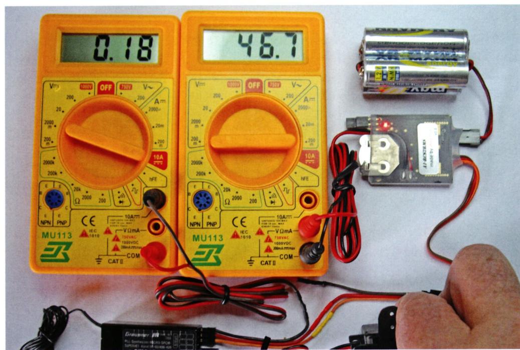
A2-RCS2RMS measurement adapter, which can be used in conjunction with an inexpensive DMM with a DC voltage range of 200 mV. The following laboratory measurement shown in Figure 3 was performed using this adapter. For a direct comparison, we looped a DMM without an RMS adapter into the circuit. We manually operated the connected digital servo so that a root mean square (RMS) current of approximately 1 ampere flowed. Figure 3 shows the remarkably large difference between the two measurements as a result.
You are now able to measure your own components to learn more about their suitability. Don’t hesitate to share and discuss your objective results with your colleagues.
In the next workshop, we’ll take a closer look at the practical significance of measuring and evaluating electrical currents in our propulsion systems. We’ve also posted an article about this workshop on our blog at blog.innoflyer.ch.
All the materials you need to replicate this workshop at home in your workshop are available at well-stocked model-making specialty stores or at www.innoflyer.ch.
Print it out and head to the hobby room www.modellflugsport.ch
To accompany this 6-part workshop series, you'll find a blog at www.innoflyer.ch where the topics covered in the magazine are explored and discussed in greater depth.


News from HEBU

TEAM MANAGER "THIS" BOSSHARD
 Rodito Nussbaumer

YOU KNOW WHAT I MEAN? 125 YEARS OF THE SWISS AERO CLUB
 Emil Giezendanner

HORIZON HOBBY/LEMACO NEWS: MICRO OV-10 BRONCO 645 MM BY E-FLITE

PRIDE AND GOOD IDEAS
 Markus Nussbaumer

34th HAHNENMOOS ALPINE MODEL AIRPLANE CAMP
Res Dauwalder
TRY-OUT DAY AT MFV WETTINGEN
Urs Keller
F3A EUROPEAN CHAMPIONSHIPS IN ST-MACAIRE, FRANCE
 Matthias Bosshard

52. 2026 ALPS CUP
Emil Giezendanner
ATOM, THE NEW DOUBLE-DECKER FROM CPLR
Matthias Bosshard
SUMMER FUN 2026 AT MG USTER
Martin Wunderli
What's New at Leomotion.com

COUPE DES ALPES – OBSERVE AND LEARN
Rodito Nussbaumer
TWIN TOWN PARTNERSHIP
Wolfgang Voeller
BY YOUTH, FOR YOUTH
Lorena Betschen
CORSAIR F4U – A WARBIRD WITH A MEMORABLE LOOK
Jürgen Rosenberger, Jürgen Prinz
SMALL, MODEL-LIKE SAILBOATS
Res Dauwalder
WELCOME, NEW MEMBER!
Andrea Bolliger
FREE FLIGHT IN THE MIDDLE OF SUMMER
Urs Muntwyler
EURO CONTEST GLIDER ACRO TOUR AUSTRIA 2026

INSIGHTS INTO THE HISTORY OF SEAPLANES

THE PC-21 STORY
Emil Giezendanner
NEWS FROM HEBU
 Julia Bucher

FROM 0 TO 100
Markus Nussbaumer
MEMORIES
Wolfgang Völler
NOS REGION – A HUB FOR ELECTRIC AVIATION
Emil Giezendanner
DO YOU KNOW WHAT I MEAN IN THE LAND OF SMILES?
Emil Giezendanner
A SPECTACULAR F3A WORLD CUP IN THE PRINCIPALITY OF LIECHTENSTEIN
Emil Giezendanner