
We're building an indoor model airplane
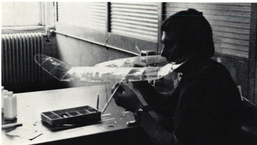
Author Werner Heise with his indoor glider model at the 1974 F1D World Championships in the U.S.
The fuselage is made from two main parts: the engine section and the tailplane spar. The fuselage tube is wound around an 8-mm metal mandrel. Sand the balsa wood down to 0.3 mm. The exact width is determined by wrapping a strip of paper around the metal tube. To wrap the balsa, moisten the balsa strip, wrap it lengthwise around the mandrel, and secure it with gauze. Let it dry in the oven for 1 hour at a maximum of 100°C. Next, apply the glue to the joint using the tip of a balsa stick (end-to-end gluing). To prevent it from sticking, rotate the metal mandrel slightly as you go. The tube is approximately 440 mm long and is cut to the final length only at the very end. Coat the finished tube with very diluted nitrocellulose lacquer. Additional weight is only 0.02 g. The fuselage cone No. 2 is constructed using the same principle, with a board thickness of 0.2 mm.
In No. 1, we glue two 0.3 mm-thick reinforcement strips vertically. We then cut the front section at an angle and finish it off with No. 4 balsa (0.3 mm).
For the wing connection tubes No. 5, made of 0.3 balsa, we wrap them wet around a 2 mm steel wire and cut them to the specified lengths after they have dried. A second method for making the tubes involves wrapping cigarette paper coated with white glue around a steel wire, twisting it slightly as you go, cutting it to length, and peeling off the paper before it dries. For both methods, the steel wire should be lightly soaped.
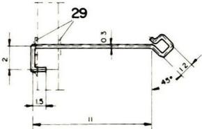
We bend bearing No. 6 for the propeller from 0.4 mm Dural sheet metal. The holes are 0.35 mm wide, and a slot is 0.25 mm wide. To allow the propeller shaft to be removed, the rear bearing is specially bent according to the drawing. We glue the finished bearing to the front of the fuselage from below so that the propeller shaft is angled 1° downward and 1° to the left—as viewed from the rear. We wrap this joint with thread from a pair of women’s pantyhose. Do not pull it too tight to avoid creating a constriction.
The rear hook No. 7 is bent from 0.3 mm steel wire according to the drawing and glued to the reinforcement board No. 3 from the rear. To prevent the rubber from breaking off, we must support the hook using the triangle No. 8 made of hard balsa.
Using a needle file, we drill holes in the fuselage No. 1 for the pylon tubes No. 5 so that the axis is positioned 90 mm behind the propeller mount. The center-to-center distance between the two tubes is 200 mm. We glue tubes No. 5 to the bottom of the
fuselage tube. While the glue is drying, make sure the pylon tubes are exactly parallel. For greater accuracy, we slide the wing spars into the pylon tubes. Next, we glue struts No. 9 and 10, made of hard balsa wood, into the fuselage according to the drawing. A 0.03 mm tungsten wire is anchored at the end of the fuselage with the hook at 360° and wound around stabilizer struts 9 and 10. At the front, the wire is pulled down along the leading edge and connected to bearing No. 6. The preload can be adjusted to different heights at position 9.
Wings. To build the wings and elevator, we need templates onto which the framework is glued. It is best to use non-warped plywood 4–6 mm thick. Watch out for eccentric wings and left-hand twist set to positive (+5 mm)! Use nylon hinges so that the wing can be built straight.
Use medium-hard balsa for the center section spars (No. 14). For the wing tips (No. 15), use slightly softer balsa. Moisten the struts No. 15 slightly with saliva and bend them around the template. Let them dry or dry them in the oven at a maximum of 100°C. Glue the struts to the template every 15 mm using thinned nitrocellulose lacquer. Sand the edge curves (No. 15) slightly outward. Glue three compression ribs (No. 16) into the bend. We fabricate the ribs for the wing and elevator using a sheet metal template. We pull the damp spars over the bent sheet metal template and secure them on both sides with a clothespin. Dry them from below over a low gas flame. First, we glue the three ribs into the kinks. Then the remaining six. Place a straight balsa strip (3 x 3 mm) on the curve and trim it to fit the trailing edge. Glue struts No. 18 into the ribs.
Elevator. The elevator is constructed using the same principle as the wing. Spine No. 22 is wet-bent around the template in two sections. The hinge is positioned in the center. Ribs No. 23 are glued between the spars. The elevator bracing No. 24 is glued in place last, after the surface has been covered.
Rudder. For the rudder, spar No. 25 is also wrapped around the prepared template. After it has dried, remove it and glue it to the template using thinned nitrocellulose lacquer. Glue in the lower limiting spar No. 26 and cover it with fabric. Stretch the film over a small frame to ensure it is sufficiently taut. The rear protruding stub of No. 25 also serves as a strut for the elevator rib 23 when gluing it to the tailplane spar No. 2.
First, we need to make some microfilm holder frames. For the altitude control, for example, with an internal width of 16 x 43 cm. For this frame, we cut balsa strips measuring 2 x 20 mm and glue them together to form a rectangle.
Fill a bathtub with water; the water temperature should match the room temperature. Once the surface is smooth and still, use a spoon to pour a few drops of the mixture described (MFS 6/75) onto it. As you pour, the drops should form a line; which then spreads quickly across the entire surface. Wait a few minutes and place the moistened frame on top. Carefully fold the overhanging microfilm over the frame. The microfilm is pulled out of the water at an angle, similar to water skiing, and stored in a dust-free place for at least one week to dry.
The wing covering should be made in two halves. The seam should be located on the wing’s center rib. First, cover the wing while it is flat. Coat the frame with saliva or beer using a fine hairbrush. Cut open one edge of the microfilm frame and pull it over the template. Blow gently to help it adhere. Trim off the excess with a sharpened balsa strip dipped in acetone. Caution! The film can melt into the frame; use only a small amount of acetone on the balsa tip. Cover the second half in the same manner, allowing a 5 mm overlap. Let all covered parts dry on the templates for 3 days.
Carefully peel the wing off the template using a razor blade. Now lift the wing center section and wingtips into their correct positions at the bend points and secure them with appropriate shims. Tension the loose film with a brush dipped in water by carefully pulling it over rib No. 16. You’ll be surprised at how taut the film becomes.
We need to build a frame for the bracing so we can position the fuselage at the correct height relative to the wing. Base board: 20 x 70 cm. See the photo for further details.
From the bottom, we glue pylon No. 20 into the correct position; likewise, yoke No. 19—also known as the strut tree. The bracing, made of 0.02–0.025 mm chrome-nickel steel wire, is now glued in place in the following order: 1. From the right outer wing bend to the front lower pylon—wrap it around once and continue to the left outer wing bend. To tension the wire, hold the spool of thread in your right hand and pull it lightly all the way tight against the frame, while using the tip of a needle in your left hand to apply glue from a small glue pot to the
joint. Hold this position for a moment—check the connection with a magnifying glass if necessary. After joining, cut the wire, leaving a 10-mm allowance. These extensions are intended to allow for any necessary adjustment of the wing’s warpage later on. 2. Wrap the left wing bend once around strut tip No. 19 and continue to the right outer wing bend. 3. Do the same on the opposite side. 4. Wrap the right wing center section around the center of the pylon and then to the left wing center section. 5. and 6. Do the same along the trailing edge. It’s difficult to define the correct tension. I apply tension by holding the wire between two fingers with a light pull.
The covered elevator and ailerons are now glued to tailplane support No. 2. Make sure the elevator is at the correct angle! After allowing it to dry thoroughly, glue the tailplane support 2 mm into the main fuselage. It’s best to use a template for this step as well.
Propeller. Make the propeller template according to the drawing. Use the same pitch for every diameter; see the formula provided. Cut 25 parts from a 10 mm hard balsa board (the pitch angle must be calculated for each part). Glue them together in a row and sand them down until a smooth surface is achieved. Cut out the outline of the propeller shape from 1.5 mm plywood and screw it to the template in the correct position using approximately four M3 countersunk screws. Now we can trace around it with wet paper using edge strip No. 31. After it has dried, remove the plywood template and glue the edge strip in place like a wing. For a continuous propeller mount (pitch not adjustable), propeller shaft No. 28 must already be installed but not yet glued in place. Glue support No. 27 to the propeller edge strip in the correct position and secure shaft No. 28 to the front vertical edge of the template. Glue the rib bend (also 3%) over the support. Glue two washers No. 29 (may also be made of celluloid) securely to shaft No. 28.
As a second option, I recommend the variable-pitch propeller. Insert the axle stubs into the tube, which is approximately 22 mm long and has a diameter of 2 x 0.3 mm.
Work on the model is now complete. What we absolutely need is a suitable transport case with the model securely fastened inside.
Here, I’ll leave it up to the model builder’s imagination. The size will be determined primarily by the number of models. For a championship, you should have at least 3 models. There should also be room for a frame with microfilm for repairs. We’ll mount the wing, along with the pylons, onto a balsa block shaped like a dovetail with a cross-section of approx.
10 x 25 mm in cross-section. We glue the counter-mold into the box so that we can slide the wing in. The fuselage is mounted on supports with rubber bands, etc.
Check the center of gravity! It should be accurate to within 5%. The model must fly on the first launch, because it’s not as finicky in flight. We wind it up to about 400 revolutions. The model should maintain at least its takeoff altitude during a left turn. If the model pitches up or dives, we can warp tail boom No. 2 using cigarette smoke. During all adjustments, please use only slow-motion movements; otherwise, the delicate model will break! We can then increase the RPM—depending on the height of the hangar. In Lakehurst, the model flew for 34 minutes and 56 seconds at 2,240 RPM with a ceiling height of 45 m.
Building a hall-flying model isn’t a superhuman feat, because the model was, after all, built by a human being. It certainly won’t work on the first try, but anyone who sees their model take flight after a great deal of patient work can rightly call themselves a master of perfection. Good luck and keep your spirits up. W. Heise
Please refer to the construction plan on the next page
POS | SUBJECT | DIMENSION | MATERIAL | QTY |
1 | BODY | 0.3 x 36 x 40 | BALSA | 1 |
2 | TAIL BOOM | 0.2x26x320 | Balsa | 1 |
3 | REINFORCEMENT STRINGER | 0.3 x 8 x 20 | BALSA | 2 |
4 | END CAP | 0.3x9x9 | BALSA | 1 |
5 | WING CONNECTION TUBING | Ø2x0.3x16 | BALSA | 2 |
6 | PROPELLER BEARING | 0.4x2x15 | ALU | 1 |
7 | REAR HOOK | Ø0.3x15 | SPRING ST | 1 |
8 | REINFORCEMENT HOOK | 0.3x2x2 | BALSA | 1 |
9 | BRACE | 0.6x0.6x25 | BALSA | 2 |
10 | STREBE | 0.6 x 0.6 x 25 | BALSA | 4 |
11 | CROSS STRUT | 0.6 x 0.6 x 32 | BALSA | 1 |
12 | CROSSBRACE | 0.6 x 0.6 x 21 | BALSA | 1 |
13 | TENSION WIRE | 0.03 x 850 | CHR NI | 1 |
14 | SPAN BEAM CENTER | 0.8x0.6x400 | BALSA | 2 |
15 | WING EDGE | 0.8 x 0.6 x 350 | BALSA | 2 |
16 | RIBBE | 0.8 x 0.4 | BALSA | 3 |
17 | RIBBE | 0.8 x 0.4 | BALSA | 6 |
18 | STRAUT | 0.4 x 0.4 | BALSA | 6 |
19 | STREBE | 0.6x0.6 | BALSA | 2 |
20 | PYLON | Ø2x85 | BALSA | 2 |
21 | TENSION WIRE | Ø0.02x850 | CHR NI ST | |
22 | HIGH-CONTROL SPAN | 0.6x0.8x | BALSA | 1 |
23 | RIBBE | 0.4 x 0.6 | BALSA | 5 |
24 | STRUT | 0.4 x 0.4 x 30 | Balsa | 2 |
25 | EDGE ARCH SIDE SUPPORT | 0.4x0.4x | BALSA | 1 |
26 | SPAR | 0.4 x 0.4 x 75 | BALSA | 1 |
27 | PROPELLER MOUNT CON. | Ø2x250 | BALSA | 2 |
28 | AXIS | Ø0.3x25 | SPRING ST | 1 |
29 | U-WASHER | Ø15x0.2 | STEEL | 2 |
30 | BEARING RUBY | 120/35 | 1 | |
31 | EDGE ARCH PROP | 0.4x0.6x | BALSA | 2 |
32 | RIBBE | 0.4x0.4 | BALSA | 10 |
CAT. F1D
FORMULA: MAXIMUM SPAN 65 cm MINIMUM CELL WEIGHT 1 g
DESIGN: SYLWESTER KUJAWA DRAWN BY: WERNER HEISE IN ISENGRIND 35/14 8046 ZURICH


News from HEBU

HORIZON HOBBY/LEMACO NEWS: MICRO OV-10 BRONCO 645 MM BY E-FLITE

PRIDE AND GOOD IDEAS
 Markus Nussbaumer

TEAM MANAGER "THIS" BOSSHARD
 Rodito Nussbaumer

YOU KNOW WHAT I MEAN? 125 YEARS OF THE SWISS AERO CLUB
 Emil Giezendanner

F3A EUROPEAN CHAMPIONSHIPS IN ST-MACAIRE, FRANCE
 Matthias Bosshard

ATOM, THE NEW DOUBLE-DECKER FROM CPLR
Matthias Bosshard
SUMMER FUN 2026 AT MG USTER
Martin Wunderli
What's New at Leomotion.com

52. 2026 ALPS CUP
Emil Giezendanner
TWIN TOWN PARTNERSHIP
Wolfgang Voeller
34th HAHNENMOOS ALPINE MODEL AIRPLANE CAMP
Res Dauwalder
CORSAIR F4U – A WARBIRD WITH A MEMORABLE LOOK
Jürgen Rosenberger, Jürgen Prinz
SMALL, MODEL-LIKE SAILBOATS
Res Dauwalder
TRY-OUT DAY AT MFV WETTINGEN
Urs Keller
WELCOME, NEW MEMBER!
Andrea Bolliger
FREE FLIGHT IN THE MIDDLE OF SUMMER
Urs Muntwyler
COUPE DES ALPES – OBSERVE AND LEARN
Rodito Nussbaumer
EURO CONTEST GLIDER ACRO TOUR AUSTRIA 2026

BY YOUTH, FOR YOUTH
Lorena Betschen
INSIGHTS INTO THE HISTORY OF SEAPLANES

THE PC-21 STORY
Emil Giezendanner
NEWS FROM HEBU
 Julia Bucher

FROM 0 TO 100
Markus Nussbaumer
MEMORIES
Wolfgang Völler
NOS REGION – A HUB FOR ELECTRIC AVIATION
Emil Giezendanner
DO YOU KNOW WHAT I MEAN IN THE LAND OF SMILES?
Emil Giezendanner
Have you almost forgotten about aircraft that take off and land vertically?
Emil Giezendanner