
A glitch?
Anyone who buys a ready-to-fly electric model airplane today can assume that the setup is more or less correct. Manufacturers have learned to match the propeller, motor, and battery so that the whole thing works without any problems. For models of a “manageable” size, this isn’t rocket science, since there are plenty of scalable components—such as propellers, motors, speed controllers, and batteries—available at affordable prices in the range up to about 500 watts. In addition, modern motors are considered robust and versatile. This also benefits those who configure their own models.
Motor speed (kv) and propeller size no longer really cause headaches (it flies, after all), so the motor and propeller are operated outside their optimal operating characteristics and thus consume an unnecessary amount of energy (which, thanks to LiPo batteries, is now readily available). With small models, which take off with relatively little power, this is less noticeable. Due to their favorable surface-to-volume ratio, small motors can be overloaded to a greater
degree. And if it just doesn’t work out, replacing a component doesn’t cost an arm and a leg. The situation is different with larger models, whose power requirements, as is well known, increase by the third power of the relevant model dimensions and thus quickly call for a more powerful battery and motor. This means that size is definitely a disadvantage. The larger the powerplant, the less favorable the surface-to-mass ratio becomes—and thus the more difficult it is to dissipate the resulting power loss. The larger the model, the more important it is to get the right setup… and the trial-and-error approach can get expensive.
Of course, the market now offers excellent motors capable of driving propellers with diameters of 20" and larger. They deliver generous torque. To achieve this with good efficiency, even high-pole machines require thick magnetic strips, solid iron cores, and substantial copper windings. This adds weight—and costs money. So anyone who appreciates the advantage of an electric drive—which is lighter than a combustion engine (yes, we’ve long since reached that point)—and also has a limited budget might be looking for alternatives. They exist in the form of the good old gear—
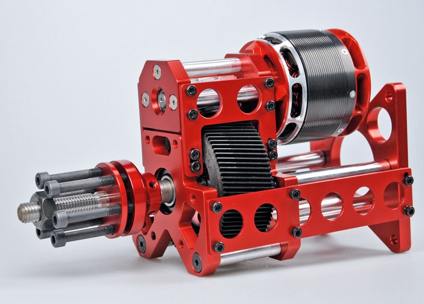
At the same time, we’re seeing a phenomenon that energy-conscious people refer to as the “rebound effect.” A common example from everyday life: Because LED bulbs are considered energy-efficient, people simply leave the lights on longer (since it “costs nothing”). As a result, despite improved efficiency, energy consumption actually increases.
Applied to model drives, this means that, thanks to robust components, by adjusting the number of cells, specific
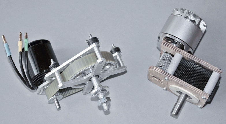
Gear solutions can also improve efficiency in electric motors, which are known for their flexibility.
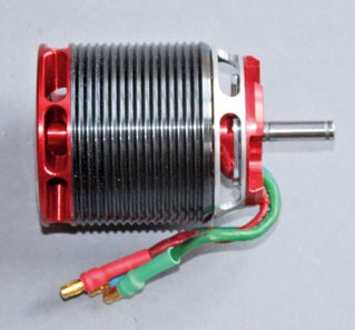
(kv 550 rpm/V) – not just for helicopter drives.
Wheel technology. The gearmotor, once thought to be obsolete, deserves a comeback.
There is sometimes a naive misconception that electric vehicles can easily do without a transmission. This is pure wishful thinking. While it is true that a DC motor delivers maximum torque right from a standstill, it does so at an unreasonably high (energy) cost. For example, in electric bicycles, the mid-drive motor, which in its...
Since it often includes multiple gear stages and makes use of the bicycle’s gearshift, it has long since surpassed the wheel-hub motor. And even wheel-hub motors, in the interest of a weight-saving design, have a speed-reducing planetary gearbox built in most cases. A motor like this simply operates more efficiently at lower speeds.
The trendy Porsche Taycan even features a two-speed transmission on the rear axle. The first gear helps the Taycan achieve even better acceleration right from the start, while the long-ratio second gear is designed to enable German autobahn speeds without field-weakening engine control.
Electric motors simply generate power more “economically” at higher speeds than they do from “built-up” torque alone. In fact, if you try to make an electric motor high in torque, you have to accept unpleasant side effects even when using powerful SE magnets. While torque does increase linearly with the current drawn, this
understandably reaches its limits quite quickly in battery operation. Conversely, one can try to “make better use” of the current by using a winding with more turns. If an electric motor is given roughly twice the number of turns, the specific torque actually doubles. All clear? Not quite, because—assuming the same physical dimensions—the winding wire will not only be twice as long but, due to the
unchanged winding space—it will also have only half the cross-sectional area. This quadruples (!) the ohmic resistance, and the increased winding resistance causes the current-dependent copper losses to rise disproportionately. That leaves the option of enlarging the machine; however, if the winding length is doubled, the resistance “only” increases to about twice its original value. To achieve this, however, the iron cores and
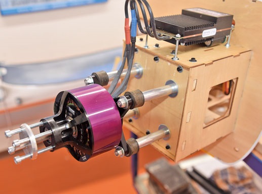
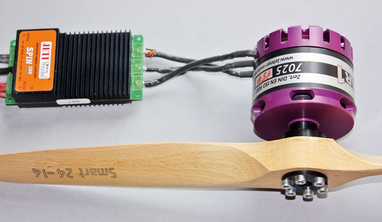
This Hacker Q80 L 135 kV motor delivers plenty of torque for propellers up to 27" in diameter. Compared to gear-driven solutions, this type of motor operates with unmatched quietness. However, this motor does weigh in at 1335 g.
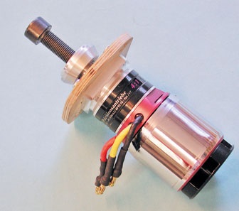
Ideal for large towed models.
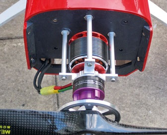
The entire supporting structure grows along with it. The machine becomes larger and heavier. Things look a little better when the motor diameter increases. When the diameter doubles, the torque does indeed increase roughly quadratically (to four times the original value); however, because the circumference also increases, it becomes necessary to divide the magnetic circuit into several segments to limit the magnetic paths. This leads to the development of multipole machines. But even these are not the solution to all problems, as the now more frequent pole changes cause more speed-dependent iron and eddy current losses. It is interesting to note that an electric motor achieves its highest efficiency in the operating range where current-dependent losses balance out speed-dependent losses. One may
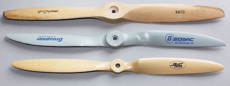
So don't "get carried away" in either direction.
Countless sets of measurements taken on various electric aircraft motors show that while our classic external-rotor motors with 14 to 28 poles achieve the best torque results, they also reach their speed (and thus voltage) limit relatively early—the point at which efficiency begins to decline again. Precisely at—
The same applies to the well-known 2-pole motors with air-gap windings (Hacker, Kontronik, Lehner), which operate efficiently only at the highest speeds and are therefore usually sold in combination with high-reduction planetary gear sets. Motors with 8 to 10 poles have received less attention so far—or so it seems, at least. They often boast maximum efficiencies of 90% and above, even at respectable current levels of 40–80 A,
—precisely the range where ambitious hobbyists like to experiment. This brings us into the realm of helicopter motors with specific RPMs as low as about 450 rpm/V, which, with a “fighting weight” of up to 500 g, can deliver several kilowatts of power output. It is no coincidence that this type of motor has evolved into a true powerhouse, as the dynamics of 3-D helicopters—triggered by abrupt pitch changes—
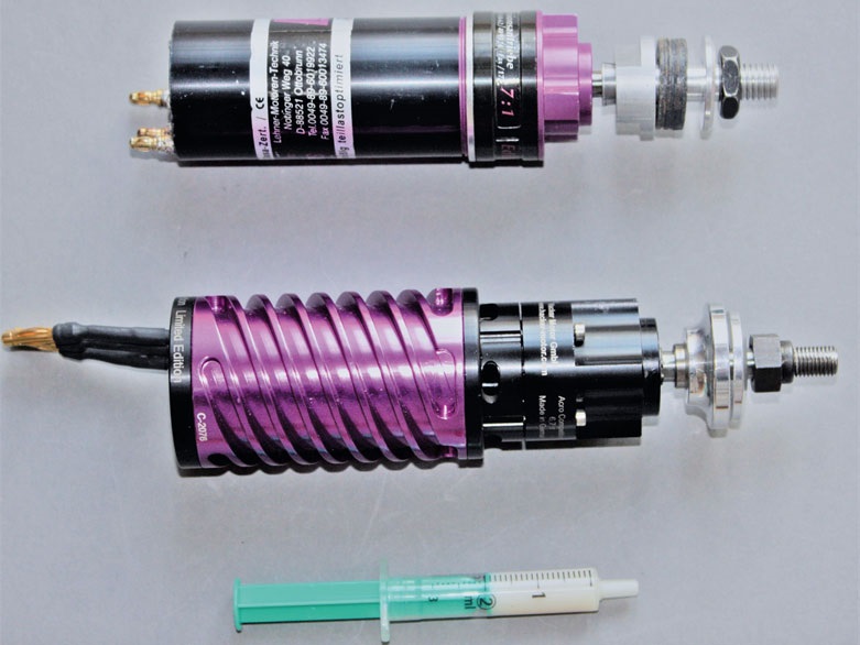
With the resulting dynamic current waveform, this places the highest demands on the motors. During the “helicopter boom,” this led to the development of some very ambitious designs. Now that this boom seems to have subsided somewhat, a new field of application is opening up for some of these powerhouses. They can truly play to their strengths at higher operating voltages with batteries ranging from 6 to 12 (14) s. And, of course, only with a gearbox that—when it comes to propeller selection—can even venture into the XXL range.
If you get everything right, you can expect the following performance figures:
- Gearbox losses are more than offset by the increased efficiency on the motor side.
- The range of applications for existing motors expands (second life).
- Larger, higher-ascent, and thus more efficient propellers can be installed (which often also better match the model’s appearance).
- The total weight of the drive system is lower, despite the added mechanical components,
than that of a direct-drive motor with comparable torque (the main benefit).
Of course, a few compromises are unavoidable. For example, installing the system into an existing model may sometimes require creative solutions when dealing with certain bulky gearbox designs. And the additional background noise is hard to deny and not always desirable.
Of course, even smooth-running transmissions don't come for free. That's why it's definitely worth taking the time to learn about the different types.
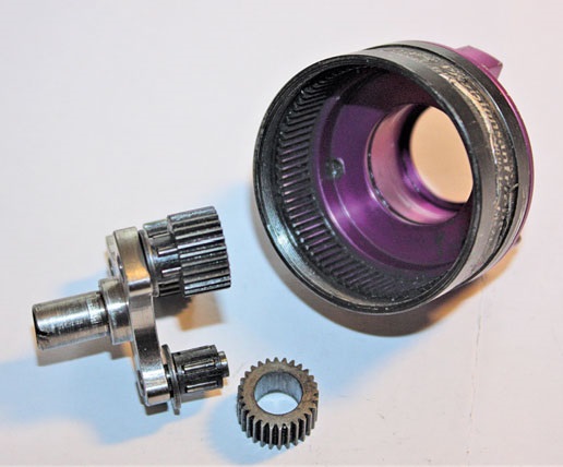
It is not without reason that the planetary gearset—whose basic operating principle can be assumed to be familiar to the reader—has enjoyed such widespread popularity to date. Such an epicyclic gearset has a compact design, exhibits no shaft misalignment, and maintains the direction of rotation. Reduction ratios of up to a factor of 8 per stage are achievable. The main advantage lies in the internal distribution of forces across typically 3 (...4) planetary gears, so that the surface pressure—and thus wear—in the area
the tooth flanks is reduced. One might find the inevitable noise to be a nuisance, as it results from the fact that only metal gears can be used at high power output levels. These units also require maintenance in the form of occasional relubrication. Nevertheless, when purchasing such units, care should be taken to use only those gearboxes whose planetary gears are equipped with roller bearings (usually needle bearings), since parts with plain bearings are prone to seizing—sometimes with serious consequences for the entire system. →
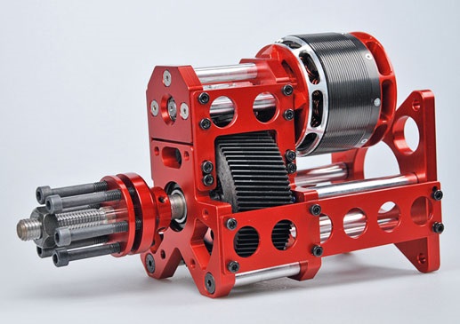
Drives with a (rounded) 7:1 reduction ratio and 2-pole squirrel-cage motors with air-gap windings are considered proven; due to physical limitations, these are designed to operate more efficiently at higher specific speeds of 1200–1800. This makes it entirely possible to efficiently move blades measuring 20" and longer. Things get even easier when using the aforementioned external-rotor motors from the rotorcraft sector, which typically feature a 3:1 to 5:1 reduction ratio.
Due to their compact outer diameters, planetary gearboxes also fit well in the nose of gliders. There, as well as with
motorized models, it sometimes makes sense to not only mount the long units at the front but also to support them at the rear to prevent a tendency to vibrate.
Commercially available motors with flanged planetary gear sets (for example, from Hacker, Kontronik, Leomotion, Plettenberg, Reisenauer, and Schambeck) are considered tried and true. Tests with industrial gearboxes—such as epicyclic gearboxes designed for roller shutter drives—have also yielded satisfactory results, but they tend to be somewhat noisier in operation due to their larger module size.
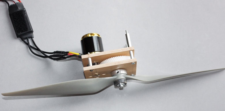
Helical gearboxes are the classic torque converters. The fact that they reverse the direction of rotation used to be a problem back when carbon-commutated motors with a preferred direction of rotation were the norm. Brushless motors rotate equally well in either direction. That leaves the inevitable shaft misalignment. In sailboat propulsion systems, this can sometimes become a problem. Of course, the issue of noise must not be swept under the rug. It’s a long-standing problem because, in the past, cheap gear sets made of brass pinions and
molded plastic gears were introduced to the market. Even things that seem as simple as two meshing gears require attention to detail. In addition to high-quality machining of the tooth flanks, reducing surface pressure through sufficient tooth width, an appropriate (not too large) module, a suitable material pairing (metal/plastic), and, above all, helical gearing to reduce the inevitable gear noise. The topic of lubrication could fill volumes, but it helps not only with friction reduction but also with noise reduction. If the gear set is enclosed, you kill two birds with one stone (is that still an expression we use today?): The vibration of the bearing shells is dampened, and the grease doesn’t splatter everywhere.
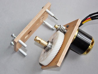
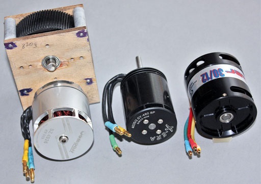
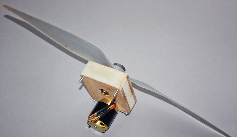
In addition to commercially available gear solutions (such as those from Kontronik), spur gearboxes can also be easily assembled yourself using suitable gear sets. The choice of material depends on the available machining options. Initial attempts with aluminum gear plates were quickly abandoned because the metal is relatively (!) heavy, barely dampens vibrations, and can even act as a soundboard. Better results were achieved with 4- to 6-mm-thick plastic plates made of polystyrene or Makrolon, although these are best machined using a CNC milling machine. However, since such services had to be “purchased,” the gear plates were initially fabricated from plywood on a trial basis. Of course, only high-quality, sturdy material comes into question here: warp-free panels made of 7–9-ply glued beech plywood with a wall thickness of 6–8 mm. And lo and behold, the result was better than expected. Thus, the “furniture” originally intended as temporary solutions turned out to be
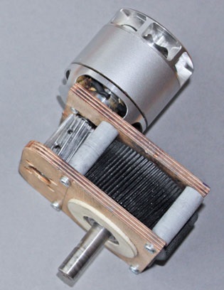
Due to its wide tooth width (30 mm), it can handle a power throughput of several kilowatts.
They can be manufactured with sufficient precision, are unbeatably lightweight, and—importantly—surprisingly quiet. The latter, of course, requires that the center distances—which determine the tooth flank clearance—be selected correctly. After all, the gears must under no circumstances jam, but they also must not have unnecessarily large clearance. The pragmatic solution here is as follows: The pinion and
the large gear are clamped together with a sturdy rubber ring, with four layers of aluminum foil (from Mom’s kitchen drawer) sandwiched in between. Afterward, the required shaft spacing can be determined by taking two measurements with a simple caliper. In case you’ve forgotten: outer shaft spacing plus inner shaft spacing, then divide the sum by two. Shaft spacing = (outer measurement + inner measurement) : 2
The real challenge now is to transfer the dimensions determined this way onto the plates as accurately as possible and to drill the holes for the ball bearings using the appropriate tools. If you can find a suitable Forstner bit, you’re in the clear. It goes without saying that the front and back sides are machined in a single operation.
When selecting the gear pair, it’s also important to avoid exact integer gear ratios, because this causes the same (potentially defective) teeth to mesh repeatedly, which can accelerate wear.
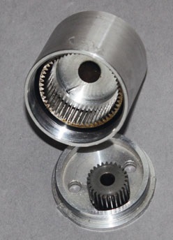
A special type is the internally geared transmission, which made a name for itself in model making during the 1990s as the “Introgear.” Despite its undeniable advantages (less shaft misalignment, no reversal of rotation, more teeth in mesh), it is now considered a dying breed.
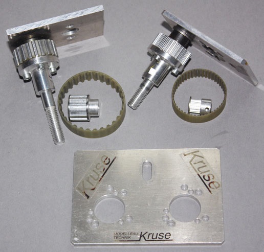
Older readers will surely still remember the Kruse gearboxes, which also date from that era. They were based on glass-fiber-reinforced timing belts and offered reduction ratios of up to 1:4, although significantly lower reduction ratios were typically used. The brush motors common at the time simply did not allow for efficient propellers with direct drive, and their speed flexibility was also limited at higher speeds. Thus, the toothed belt drive was a popular means of driving reasonable propeller sizes even with ferrite motors. Twin-motor propulsion systems also became possible. However, even this type seems to have quickly disappeared from airfields following the meteorite impact of the multipole outrunner motors.
Whether there will be a widespread resurgence of belt drives remains to be seen at this point, since timing belt drives—with their maximum shaft misalignment—can never be built compactly and are better suited for low rotational speeds, both for reasons of efficiency and because of the sometimes underestimated noise they generate. Furthermore, belts are commercially available only in specific tooth counts or lengths, which then requires mechanical compensatory measures such as tension pulleys or adjustable shafts. Nevertheless, such a reduction ratio can still be useful today when switching to large propellers with an approximately square pitch-to-diameter ratio, as this is the only way to efficiently convert air movement into propulsion.
So there are certainly alternatives to electric propulsion systems in model aviation. After all, sometimes instead of digging deep into your hobby budget, you can simply give some serious thought to alternative propulsion options. And for some motors that had previously lost their appeal, a new and challenging field of application beckons. In this age of the throwaway society, aren’t these encouraging prospects?


News from HEBU

TEAM MANAGER "THIS" BOSSHARD
 Rodito Nussbaumer

YOU KNOW WHAT I MEAN? 125 YEARS OF THE SWISS AERO CLUB
 Emil Giezendanner

F3A EUROPEAN CHAMPIONSHIPS IN ST-MACAIRE, FRANCE
 Matthias Bosshard

52. 2026 ALPS CUP
Emil Giezendanner
PRIDE AND GOOD IDEAS
 Markus Nussbaumer

ATOM, THE NEW DOUBLE-DECKER FROM CPLR
Matthias Bosshard
CORSAIR F4U – A WARBIRD WITH A MEMORABLE LOOK
Jürgen Rosenberger, Jürgen Prinz
SUMMER FUN 2026 AT MG USTER
Martin Wunderli
TRY-OUT DAY AT MFV WETTINGEN
Urs Keller
TWIN TOWN PARTNERSHIP
Wolfgang Voeller
BY YOUTH, FOR YOUTH
Lorena Betschen
SMALL, MODEL-LIKE SAILBOATS
Res Dauwalder
What's New at Leomotion.com

HORIZON HOBBY/LEMACO NEWS: MICRO OV-10 BRONCO 645 MM BY E-FLITE

COUPE DES ALPES – OBSERVE AND LEARN
Rodito Nussbaumer
EURO CONTEST GLIDER ACRO TOUR AUSTRIA 2026

INSIGHTS INTO THE HISTORY OF SEAPLANES

34th HAHNENMOOS ALPINE MODEL AIRPLANE CAMP
Res Dauwalder
WELCOME, NEW MEMBER!
Andrea Bolliger
FREE FLIGHT IN THE MIDDLE OF SUMMER
Urs Muntwyler
THE PC-21 STORY
Emil Giezendanner
NEWS FROM HEBU
 Julia Bucher

FROM 0 TO 100
Markus Nussbaumer
MEMORIES
Wolfgang Völler
NOS REGION – A HUB FOR ELECTRIC AVIATION
Emil Giezendanner
Have you almost forgotten about aircraft that take off and land vertically?
Emil Giezendanner
DO YOU KNOW WHAT I MEAN IN THE LAND OF SMILES?
Emil Giezendanner