
Wakefield Rubber-Powered Model F1B
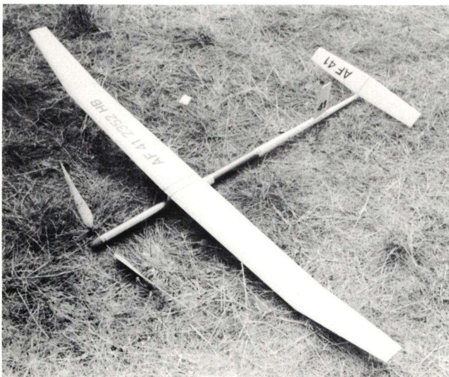
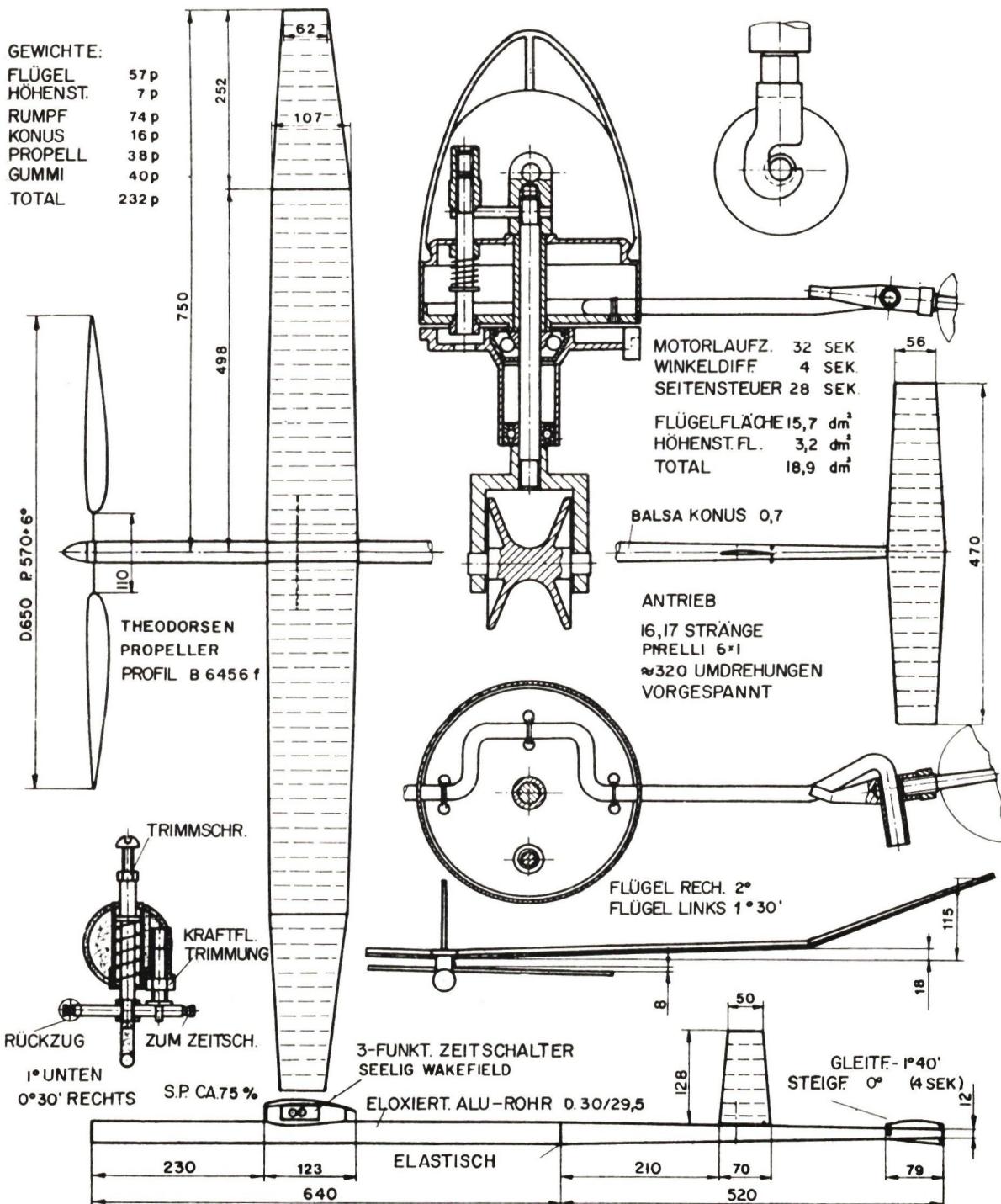
The enclosed construction plan shows Dieter Siebenmann's rubber-powered model. This model was named "Model of the Year" by the international jury at the 1969 World Championship in Prague.
| Total wing and elevator area | 17–19 dm² |
| Minimum weight | 230 g |
| Maximum weight of the lubricated rubber cord | 40 g |
We haven’t held a regional competition in the VM–GM (F1B, F1C) categories for 7 years—which is a shame for these interesting categories. We hope that some model aircraft enthusiasts will decide to build such a model.
Building a rubber-powered model requires a great deal of skill and perseverance. This also applies later on during the flight-testing phase. I therefore recommend this category only to experienced model builders. Furthermore, as you can see from the plans shown, there are many mechanical parts that need to be fabricated. If you can’t turn parts yourself, you might know a precision machinist. The fuselage tube (Ø30 x 0.3) can be obtained from Dieter Siebenmann while supplies last and is world-renowned.
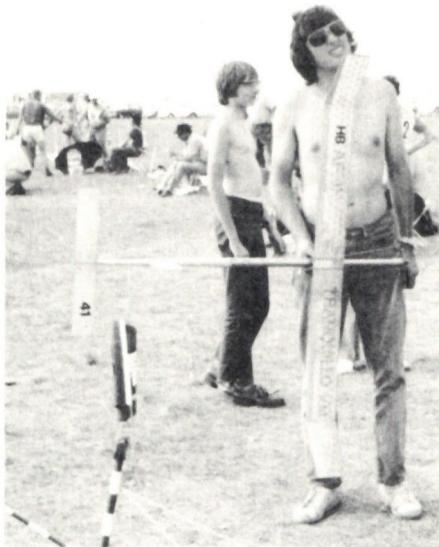
For the wing assembly, we use a 2-cm-thick blockboard as the base. The wing is constructed in four parts. We then glue 6-mm-thick, soft balsa wood onto the blockboard, cutting it to the size of the respective wing shape. A profiled negative mold is screwed onto both end faces. Using a long sanding block measuring approximately 1.5/6 x 60 cm, we can now shape out the entire negative mold. Now we begin to assemble the airframe. The lower balsa board is sanded according to the plan, and we glue the front and tail spars onto it. The entire assembly is glued to the negative mold using small drops of glue, positioned so that we can easily remove the glue drops later with a razor blade. Next, use a curved ruler to cut the undersides of the ribs and glue them onto the wing form. Once all the ribs are in place, screw a second set of profiles to the front end of the upper wing surface. Using the long sanding block, you can now carefully shape out the top surface. To attach the upper skin, we use contact adhesive, position the small board at the front spar, and spread the adhesive evenly toward the rear.
The elevator and ailerons are also constructed in the same way.
For the fuselage cone, we need a mandrel as a form. A pre-cut balsa strip (0.8 mm) is wet-wrapped around the mandrel using gauze bandages. Glue the ends together butt-jointed only after it has dried. For the aileron shaft and the elevator mounts, reinforcement rings made of balsa wood must be glued in place. To cap the cone, glue the aluminum part in place using Araldit, following the drawing. Important: Be sure to thread all the wires beforehand for the ailerons, differential control, and thermal safety device.
A Seeling (Germany) 3-function timer is installed in the pylon (wing mounting). The wing mounting consists of steel wire (1.5 mm) — with the corresponding MS tubes (preferably aluminum-reinforced) at the wing center sections. Aluminum parts should be anodized; this makes them more durable and provides additional reinforcement, especially for the fuselage. All shell parts are coated twice with two-component clear coat. Use the thinnest possible consistency (available from J. Maeder, Zurich).
The next issue will cover the construction of the propeller blades and test flights. W. Heise
| WING | 57 p |
| HEIGHT | 7 p |
| FUSELAGE | 74 p |
| CONE | 16 p |
| PROPELLER | 38 p |
| RUBBER | 40 p |
| TOTAL | 232 p |


News from HEBU

TEAM MANAGER "THIS" BOSSHARD
 Rodito Nussbaumer

YOU KNOW WHAT I MEAN? 125 YEARS OF THE SWISS AERO CLUB
 Emil Giezendanner

PRIDE AND GOOD IDEAS
 Markus Nussbaumer

ATOM, THE NEW DOUBLE-DECKER FROM CPLR
 Matthias Bosshard

SUMMER FUN 2026 AT MG USTER
Martin Wunderli
F3A EUROPEAN CHAMPIONSHIPS IN ST-MACAIRE, FRANCE
Matthias Bosshard
52. 2026 ALPS CUP
Emil Giezendanner
TWIN TOWN PARTNERSHIP
Wolfgang Voeller
CORSAIR F4U – A WARBIRD WITH A MEMORABLE LOOK
Jürgen Rosenberger, Jürgen Prinz
TRY-OUT DAY AT MFV WETTINGEN
Urs Keller
HORIZON HOBBY/LEMACO NEWS: MICRO OV-10 BRONCO 645 MM BY E-FLITE

EURO CONTEST GLIDER ACRO TOUR AUSTRIA 2026

BY YOUTH, FOR YOUTH
Lorena Betschen
INSIGHTS INTO THE HISTORY OF SEAPLANES

SMALL, MODEL-LIKE SAILBOATS
Res Dauwalder
What's New at Leomotion.com

COUPE DES ALPES – OBSERVE AND LEARN
Rodito Nussbaumer
34th HAHNENMOOS ALPINE MODEL AIRPLANE CAMP
Res Dauwalder
WELCOME, NEW MEMBER!
Andrea Bolliger
FREE FLIGHT IN THE MIDDLE OF SUMMER
Urs Muntwyler
THE PC-21 STORY
Emil Giezendanner
NEWS FROM HEBU
 Julia Bucher

FROM 0 TO 100
Markus Nussbaumer
MEMORIES
Wolfgang Völler
NOS REGION – A HUB FOR ELECTRIC AVIATION
Emil Giezendanner
Have you almost forgotten about aircraft that take off and land vertically?
Emil Giezendanner
DO YOU KNOW WHAT I MEAN IN THE LAND OF SMILES?
Emil Giezendanner