
Electronic Fuel Level Warning System
"How long have I been up here?" was surely the anxious question you asked yourself during your first flight. The answer was, "No idea!" because your instructor had also forgotten to look at his watch in all the excitement.
If you fly a regular training program with your glider, you’ll soon develop a feel for landing on time even without a watch. If the engine happens to cut out, it’s usually no big deal: with a little luck, you’ll even be able to bring your fast delta glider back safely to the runway.
For now, the situation is quite different with helicopters. An engine failure is usually associated with a serious crash. I say “for now” because, as of yet, there is no proven system that allows for safe autorotation landings.
Let’s say, over the course of your career as a helicopter pilot, you wear out three sets of rotor blades because you’re flying overtime. Then you’ve gotten off easy—just imagine a total loss! Still—you’ve spent so much more time and money than would have been necessary for a reliable fuel warning system. Based on these considerations, I came to the conclusion that a fuel warning system is an indispensable piece of equipment, especially for beginners in helicopter flying.
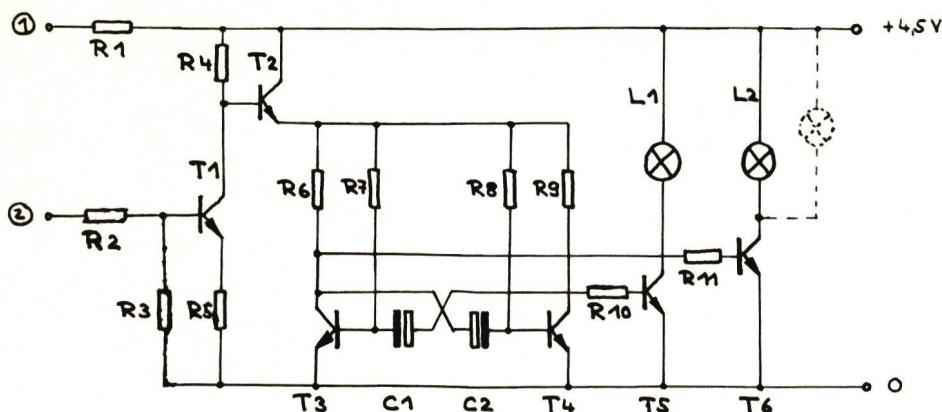
So the decision has been made: We’re going to build an electronic system that uses a flashing light to indicate when the fuel level has dropped below a certain minimum. This circuit is so simple that it can be built without a measuring instrument. If you wire the specified components correctly according to the schematic, the flashing system is guaranteed to work.
Inputs 1 and 2 are connected to the fuel tank sensor, which changes its resistance depending on the fuel level.
When both electrodes are submerged in the fuel mixture, the resistance is approximately 20 ks. If the fuel level drops below level A, the system goes into idle mode. When the probe is submerged, a tiny current flows through the electrodes; this current is amplified by transistor T1 and triggers the astable multivibrator via T2. The multivibrator (composed of T 3, T 4, C 1, C 2, and R 6–R 9) controls the indicator lights via the two medium-power transistors T 5 and T 6.
| R 1 | 5.6 kΩ |
| R 2 | 5.6 kΩ |
| R 3 | 1 MΩ |
| R 4 | 33 kΩ |
| R 5 | 5.6 kΩ |
| R 6 | 330 Ω |
| R 7 | 6.8 kΩ |
| R 8 | 6.8 kΩ |
| R 9 | 330 Ω |
| R 10 | 1 kΩ |
| R 11 | 1 kΩ |
| C 1 | 50 uF/3V |
| C 2 | 50 uF/3V |
| T 1 | BC 148 B |
| T 2 | BC 148 B |
| T 3 | BC 107 |
| T 4 | BC 107 |
| T 5 | 2N 1893 |
| T 6 | 2N 1893 |
| L 1 | 3.8V/0.07A |
| L 2 | 3.8V/0.07A |
This electronics system has proven reliable so far, with no failures during many hours of flight. I use a 4.5 V dry cell battery to power it. Since the circuit draws only a few mA of current when the tank is full, such a battery lasts for many hours.
In addition to the listed components, you’ll only need a soldering iron and a piece of Veroboard (a hardboard with printed circuit traces). You can purchase the components at an electronics store (e.g., Pusterla in Zurich) for about Fr. 12.—.
It’s best to start the assembly with the probe inputs and then wire the rest step by step to the right, following the schematic.
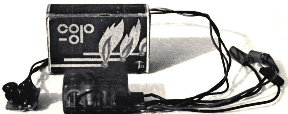
The only critical component in the entire setup is the indicator lights. It is essential that they be mounted on a soft foam rubber base; otherwise, the filaments will break due to vibrations after only a short time. Install at least two lights—this provides double the reliability and also looks good. If you want to use more than two bulbs, you can connect them in parallel with the others without any concerns. (See the diagram -----).
And now, enjoy your helicopter flying!
J. Steinmann
The author will be happy to provide further information.
Jürg Steinmann, Tel. 01/26 81 17
Bucheggstr. 24, 8037 Zurich


News from HEBU

TEAM MANAGER "THIS" BOSSHARD
 Rodito Nussbaumer

YOU KNOW WHAT I MEAN? 125 YEARS OF THE SWISS AERO CLUB
 Emil Giezendanner

HORIZON HOBBY/LEMACO NEWS: MICRO OV-10 BRONCO 645 MM BY E-FLITE

PRIDE AND GOOD IDEAS
 Markus Nussbaumer

TRY-OUT DAY AT MFV WETTINGEN
Urs Keller
F3A EUROPEAN CHAMPIONSHIPS IN ST-MACAIRE, FRANCE
 Matthias Bosshard

52. 2026 ALPS CUP
Emil Giezendanner
ATOM, THE NEW DOUBLE-DECKER FROM CPLR
Matthias Bosshard
SUMMER FUN 2026 AT MG USTER
Martin Wunderli
What's New at Leomotion.com

COUPE DES ALPES – OBSERVE AND LEARN
Rodito Nussbaumer
TWIN TOWN PARTNERSHIP
Wolfgang Voeller
BY YOUTH, FOR YOUTH
Lorena Betschen
34th HAHNENMOOS ALPINE MODEL AIRPLANE CAMP
Res Dauwalder
CORSAIR F4U – A WARBIRD WITH A MEMORABLE LOOK
Jürgen Rosenberger, Jürgen Prinz
SMALL, MODEL-LIKE SAILBOATS
Res Dauwalder
WELCOME, NEW MEMBER!
Andrea Bolliger
FREE FLIGHT IN THE MIDDLE OF SUMMER
Urs Muntwyler
EURO CONTEST GLIDER ACRO TOUR AUSTRIA 2026

INSIGHTS INTO THE HISTORY OF SEAPLANES

THE PC-21 STORY
Emil Giezendanner
NEWS FROM HEBU
 Julia Bucher

FROM 0 TO 100
Markus Nussbaumer
MEMORIES
Wolfgang Völler
NOS REGION – A HUB FOR ELECTRIC AVIATION
Emil Giezendanner
DO YOU KNOW WHAT I MEAN IN THE LAND OF SMILES?
Emil Giezendanner
A SPECTACULAR F3A WORLD CUP IN THE PRINCIPALITY OF LIECHTENSTEIN
Emil Giezendanner