
The Dream of an Overnight Success
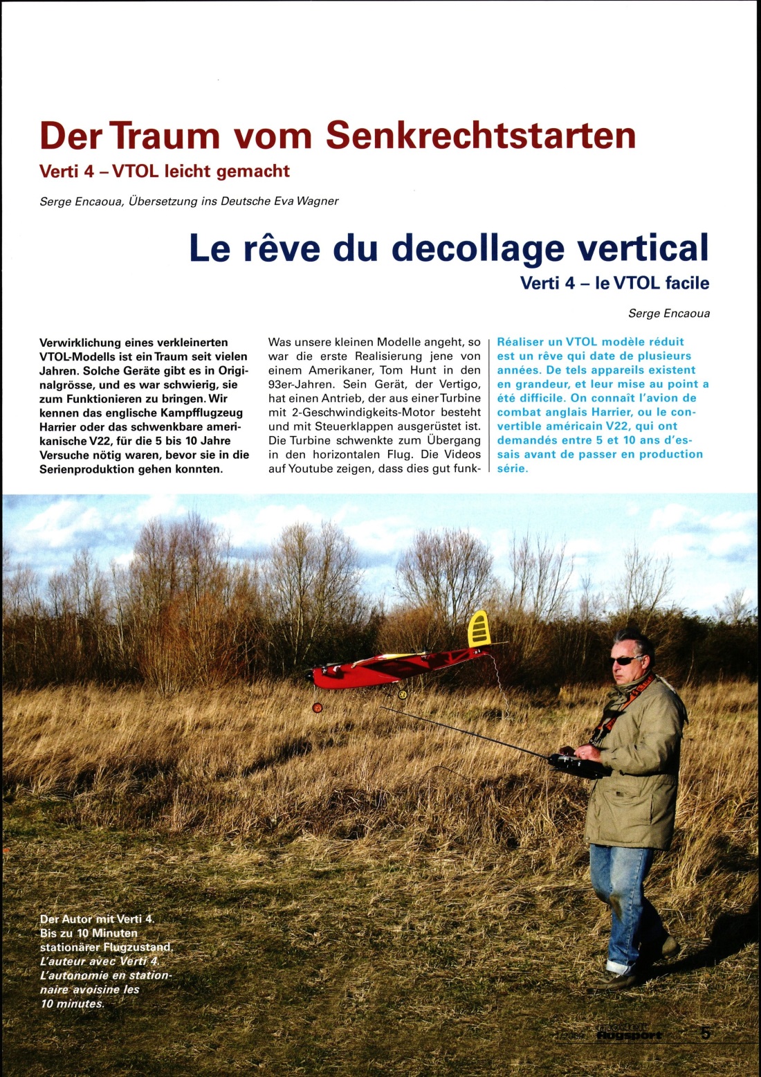
Building a scaled-down VTOL model has been a dream for many years. Full-scale versions of such aircraft exist, and getting them to work has been difficult. We’re familiar with the British Harrier fighter jet and the American V-22 tiltrotor, both of which required 5 to 10 years of testing before they could enter mass production.
As for our small models, the first one to be built was by an American, Tom Hunt, in the 1990s. His aircraft, the Vertigo, has a propulsion system consisting of a turbine with a two-speed motor and is equipped with control flaps. The turbine would pivot to transition to horizontal flight. The videos on YouTube show that this works well. Over time, advances in scaled-down models—and particularly in electronics—have made it possible to envision the construction of an electrically powered VTOL. After a few unsuccessful attempts, which I’ll tell you about in a moment, the Verti 4 saw the light of day.
My first model, developed in 1995, was a hang glider with a 10-cm³ engine and a horizontal propeller mounted at the center of gravity. The propeller’s airflow directed air to the wing tips to provide roll control, as well as to the ends of the fuselage to provide pitch and yaw control. For level flight, a flap system under the fuselage directed the airflow into a horizontal nozzle. This design was quite complex, and after several unsuccessful attempts, I realized it was uncontrollable due to the lack of efficiency in the stabilizing elements. I learned a lesson from this first unfortunate experience: it is absolutely necessary to use the motor’s power directly to maintain sufficient control.
The advent of high-performance electric motors and NiMH batteries convinced me to continue my experiments with electric models. The following model incorporated the V-22 principle with swivel motors. During roll, the motor thrust directly controlled this axis, and during yaw, control was achieved through differential swiveling of the motors. To control pitch oscillations, deflection flaps were installed behind the propellers, as low as possible to maximize the lever arm. Flight tests revealed an aircraft that was stable in roll but difficult to control in pitch due to the lack of efficiency of the deflection flaps. I doubled the number of flaps, but without much success. Overall, the design remained complex, particularly due to the cable routing and the rotation mechanism in the wing. The third model was designed based on a “duck” configuration: The idea was to simplify the design by taking advantage of the unique characteristics of the duck-wing aircraft—with the center of gravity located between the wing and the tail, the engine mechanism at this point was much easier to implement.
In the first version, the two engines were placed one above the other, rotating in opposite directions to compensate for the propellers’ torque. Pitch and roll control was achieved through a flap mechanism installed behind the engines. Yaw control was achieved through differential throttle, as in helicopters with coaxial twin rotors. I managed to experiment a little with stationary flight, but the controls were too sensitive as soon as the aircraft tilted even slightly. I revised the design by repositioning the motors; this allowed for roll control via motor RPM and yaw control via differential motor tilt. For pitch control, I used a Trex anticouple, whose step control was managed by a gyro heading lock. This worked very well in hovering flight, but the heading lock during translational flight concerned me. I eventually gave up, and the idea for the Verti 4 came to mind.
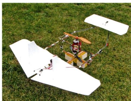
The main idea behind the Verti 4 is, above all, to make it accessible to all model builders in terms of its implementation, and to ensure that the device can be used under a variety of climatic conditions. To achieve this goal, I have set the following criteria for myself:
- A design that avoids the need to manufacture a special electronics board. All electronic mixes must be performed from the RC transmitter.
- A virtually standard airframe, but a new type of aircraft.
- Stability in stationary flight, ensuring good stability even in windy conditions.
You will see later that all of these goals were achieved.
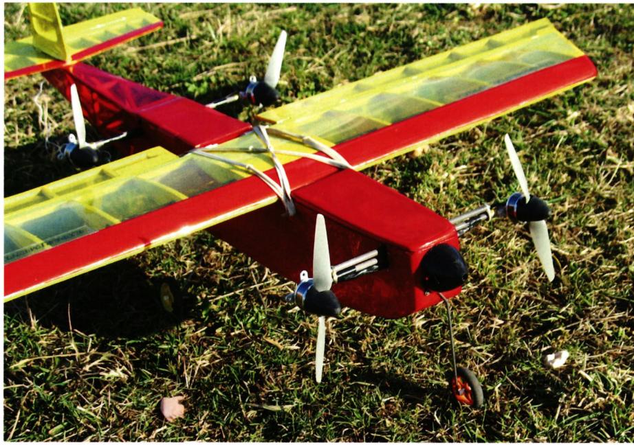
The Verti 4 features four identical motors mounted on the fuselage around the center of gravity, each with a propeller. This arrangement is mechanically simple, which greatly simplifies the design. The principle of using four propellers allows the load on each propeller to be kept low, thereby ensuring good overall performance. These propellers remain small (6×4), making it possible to mount them closer to the fuselage and protect them in the event of an impact. Small propellers also allow for easy takeoff and “normal” landing.
Yaw control is achieved through differential pitch of the front motors. Note that the propellers rotate in opposite directions; they can be ordered directly from the APC website (P stands for “pusher”).
To transition to normal flight, simply swivel the motors forward. The two rear motors are linked together, so a single servo is sufficient; however, since the two front motors are independent, two servos are needed to ensure yaw control through differential swiveling. Control during stationary flight is provided solely by the two front motors, which ensure pitch control through simultaneous control and roll control through differential control. Each of the front motors is connected to a gyroscope that controls throttle; each gyroscope is therefore mounted at a 45° angle to the fuselage axis. However, this does not apply to yaw, because this axis is naturally well damped by the vertical stabilizer. The entire setup requires 8 channels (2+1 for the motors, 3 for the swivel servos, 1 for the elevator, 1 for the ailerons) as well as a transmitter that allows for some flexibility when programming the mixers. (I have a Royal Evo 9—it’s very handy.) The vertical stabilizer isn’t controlled, but you can add that functionality if you want.
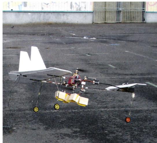
I used the Drive Calc software to design the propulsion system. It is available for free online and has a database that updates continuously and automatically when connected to the Internet. The results align well with the observed values. The following figure shows the results of the calculations for a motor in steady-state flight. The 6×4 APC propeller rotates at 7,600 rpm, generating a thrust of 220 g while consuming 35 W. The efficiency is 70%, close to the maximum efficiency of 75%. The required voltage is 6 V, which is easily achieved with a 3S battery. A quick calculation shows that a 1,800 mAh battery can keep the Verti 4 in stationary flight for about 10 minutes, and this has been confirmed in tests.
Using a simulation not shown here, a maximum single thrust of 500 g can be achieved (i.e., a total of 2000 g). The power reserve is more than sufficient; you should limit the throttle control to a total thrust of 1,500 g, which is more than enough in practice. The advantage of having this power reserve—in combination with small propellers—is that you can climb with the engines running at very high RPM while the gyroscope is engaged, thereby achieving good stability.
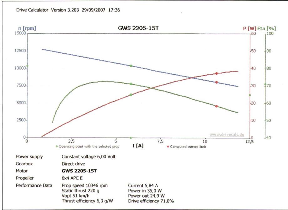
The design is that of a standard airplane with a wingspan of 1 m or more. I’ll limit myself to explaining the key points.
The wings, fuselage, and tail surfaces are covered with Oracover, which isn’t the lightest covering, but it is weather-resistant and reinforces the structure. Tip: It’s important to use lightweight balsa wood for the ribs, formers, and tail surfaces. Light balsa wood can be recognized by its lighter color.
The airfoil used is a conventional symmetrical NACA 2410, the trailing edge of which remains flat for the ailerons, which are constructed with spars made of hard balsa wood. The spar consists of a 6-mm-diameter CFRP tube.
RAS
This is really the only specialized part of the VTOL, but the design is such that the motor rotation mechanisms can be installed on one side and the rest of the “classic” fuselage on the other.
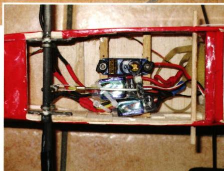
Let’s start with the motor housings: The GWS 2205/15 T motors initially run with their shafts reversed. This is quite simple—just unscrew the two rings, remove the motor shaft, and then reinsert it. Take this opportunity to clean the inside of the motor housing with a cotton swab dipped in alcohol. The propellers are then mounted on the shaft; you may need to drill them out to a slightly larger diameter. The motors are mounted on the carbon shaft using a commercially available aluminum cross bracket. The cross-brace is attached to the carbon fiber shaft, which is reinforced at this point with an aluminum tube. This tube is secured to the motor at the other end with a screw that passes through the carbon fiber shaft and through the cross-brace. This utilizes the full stiffness of the carbon tube to hold the motor and reinforce the cross bracket. This assembly is built separately. For these fastenings, a very strong Dacron line (fishing line) is used, secured with cyanoacrylate. The rear motors are mounted on a 6-mm carbon tube (at the height of the arrow), mounted on two ball bearings with an inner diameter of 6. A carbon tube of the same diameter, mounted in parallel, serves as a support rod to which the ball bearings are attached. The servo actuates a lever made of plywood reinforced with carbon fiber, which is drilled to the exact diameter to prevent any play. This tube is secured between the sides of the fuselage. As for the front motors, assembly is done in the same way, but with one small difference: there are two independent axles, one per motor. Each axle is mounted on two bearings, which are secured to the support rod with ties. Each mechanism is inserted into a pre-cut recess in the fuselage. A carbon tube, attached at a right angle to the tube, is glued to the fuselage wall with epoxy resin. The fuselage structure itself is quite conventional: the sides, made of lightweight balsa wood, are reinforced with plywood at strategic points (wing attachment, motor shaft passages, and landing gear). The rear section of the fuselage is a lattice structure made of hard balsa wood rods, with balsa wood reinforcement at the tail unit mounts. The frames are made of balsa wood, doubled on the sides with plywood and hollowed out. The two gyros, mounted at a 45° angle to the fuselage axis, are installed on a 6-mm Depron sheet, which dampens vibrations very effectively. A good adhesive for Depron and for attaching the gyros to the Depron is Fortissimo by Sader, which bonds firmly while retaining a certain degree of elasticity.
The 1,800-mAh battery is mounted on the rear of the fuselage; its placement is used to fine-tune the balance.
| Weight: | 800 g |
| Wingspan: | 1000 mm |
| Length: | 759 mm |
| Radio: | 8-channel Hyperion HP DSP 8FS receiver |
| Servos: | Ailerons, Elevator: 5 g 3×Swivel Servos: Waypoint W-150MG with metal gears 15.6 g |
| Motors: | 4× GWS 2205/15T |
| Gearboxes: | 4× Tower Pro Mac 8 |
| Propellers: | Two 6×4 propellers, two 6×4 P propellers |
| Batteries: | Lipo 3S 1800 mAh |
| Gyros: | 2× GWS PG 03 |
It is important to check and adjust the position of the center of gravity relative to the drive batteries in the fuselage. It is located exactly midway between the front and rear motor axes. Verify that the range of motion of the motors between the stationary position and the position during horizontal flight is 90°. As for yaw control, make sure to achieve a differential symmetrical yaw of 15° between the front motors, and check the symmetry of the yaw between the motors. Checking the gyroscopes’ control direction: When the aircraft is pitched forward, both front motors increase their RPM; when banking to the right during roll, the right motor increases its RPM while the left motor decreases it. Sensitivity is adjusted to achieve a gain that produces a slight oscillation. In practice, the gain is 75% and is identical on both channels.
Engine adjustment: Set the throttle to idle (about half throttle) and check whether the RPM of the four engines is noticeably the same at approximately 200 RPM. If the deviation is greater, this means that one of the engines is not functioning properly.
To control the device, you need to be able to fly a newly built airplane and keep a helicopter in simple hovering flight, because the responses during hovering are identical. The very first time I tested it was in my backyard, in light, gusty winds, and I had it under control right away. It’s inherently very stable, though somewhat flexible and more sensitive to wind than a helicopter—because of the wing, which catches the wind.
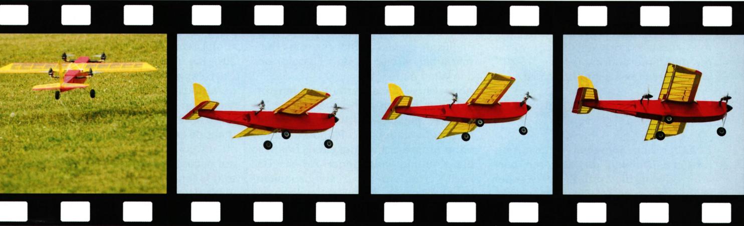
Encouraged by these results, I headed straight out into the open to test it further. I was again able to perform several hovering flights without much difficulty. That was the culmination of years of work! Afterward, to withstand the wind, I added the elevator to control the motor’s pitch. This is very efficient and allows for flying in absolutely any weather, even in strong turbulence. It’s important to note that in strong winds during stationary flight, the normal control surfaces come in handy! I then moved on to normal flight to adjust the trim; as before, I wasn’t caught off guard during the transition. It behaves like a newly built airplane; taking off from grass at half throttle is a mere formality, completed within 10 meters. It responds gently to the controls, and you can fly smoothly with just a little throttle. After a few minutes of flight, I decided to land it. And now the big moment: an attempt to transition from stationary to level flight. You wonder what kind of response such an aircraft might give. That’s the fear of the unknown. I took off again in stationary flight, climbed to about 15 m, and swiveled the engines to 45°: It immediately picked up speed, continued flying, and I observed a significant stall moment that required initiating a steep nosedive along the entire flight path. After swiveling the engines 90°, this disappears. The explanation I’ve found is known in technical terms as jet interaction. When the air jets are deflected by the engines tilted at 45°, the same thing happens as if the wing were equipped with flaps, which, as is well known, induce a stall moment. The best solution is to swivel the engines quickly to avoid this effect.
The transition from horizontal to vertical flight occurs without difficulty. The aircraft decelerates very rapidly within a few meters; a stall moment occurs that must be counteracted, and one must remember to reduce throttle to half to regain control during stationary flight. A slight “dry blade” phenomenon is observed at the very beginning of the descent, but it subsides quickly. The aircraft is very robust. Because I had initially wired the gyroscopes incorrectly, I ended up hitting the ground several times. The only damage was to the stabilizer fin, despite the violent impact.
The aircraft has already won two awards: one at the electric aircraft competition in Crespierre (France) in May 2008, and another at InterEx in Boissy Saint Yon (France) in September 2008. Check out the videos on the website http://Verti 4.blogspot.com
Have a great flight!


News from HEBU

TEAM MANAGER "THIS" BOSSHARD
 Rodito Nussbaumer

YOU KNOW WHAT I MEAN? 125 YEARS OF THE SWISS AERO CLUB
 Emil Giezendanner

SUMMER FUN 2026 AT MG USTER
Martin Wunderli
F3A EUROPEAN CHAMPIONSHIPS IN ST-MACAIRE, FRANCE
 Matthias Bosshard

52. 2026 ALPS CUP
Emil Giezendanner
PRIDE AND GOOD IDEAS
 Markus Nussbaumer

ATOM, THE NEW DOUBLE-DECKER FROM CPLR
Matthias Bosshard
CORSAIR F4U – A WARBIRD WITH A MEMORABLE LOOK
Jürgen Rosenberger, Jürgen Prinz
TRY-OUT DAY AT MFV WETTINGEN
Urs Keller
TWIN TOWN PARTNERSHIP
Wolfgang Voeller
BY YOUTH, FOR YOUTH
Lorena Betschen
INSIGHTS INTO THE HISTORY OF SEAPLANES

SMALL, MODEL-LIKE SAILBOATS
Res Dauwalder
What's New at Leomotion.com

HORIZON HOBBY/LEMACO NEWS: MICRO OV-10 BRONCO 645 MM BY E-FLITE

COUPE DES ALPES – OBSERVE AND LEARN
Rodito Nussbaumer
EURO CONTEST GLIDER ACRO TOUR AUSTRIA 2026

34th HAHNENMOOS ALPINE MODEL AIRPLANE CAMP
Res Dauwalder
WELCOME, NEW MEMBER!
Andrea Bolliger
FREE FLIGHT IN THE MIDDLE OF SUMMER
Urs Muntwyler
THE PC-21 STORY
Emil Giezendanner
NEWS FROM HEBU
 Julia Bucher

FROM 0 TO 100
Markus Nussbaumer
MEMORIES
Wolfgang Völler
NOS REGION – A HUB FOR ELECTRIC AVIATION
Emil Giezendanner
Have you almost forgotten about aircraft that take off and land vertically?
Emil Giezendanner
DO YOU KNOW WHAT I MEAN IN THE LAND OF SMILES?
Emil Giezendanner