
On the Design of Wing Struts for Large Glider Models
At a time when more and more model builders are investing significant sums in the purchase of ready-made large gliders, one might wonder whether it still makes sense to describe a construction technique using spars. The following lines confirm this, because one still encounters “true and dedicated” model builders who develop and build their own models, both to save money and for the joy of creation. Moreover, when it comes to exceptional models, one would rather undertake the construction oneself and thus avoid buying a Trojan horse whose contents—or rather, what lies within its wings—are unknown. I had the opportunity to witness a wing fracture on a Duo Discus with a 6.7-meter wingspan
at medium speed—a model that came from a German manufacturer known for its large gliders. The wing’s design was such that I would not have used it for building a model with a 4-meter wingspan. However, one should not fall into the other extreme, which is sometimes described in specialty magazines, where the model builder speaks very proudly of his concrete wing (the omission of rebar is astonishing: unreinforced concrete is not very strong!). If a wing has to be “reinforced with concrete” to withstand the stresses of vigorous flight, that means its aerodynamic design is flawed—often due to a combination of airfoils with curvatures and lift coefficients that are not in the least bit different.
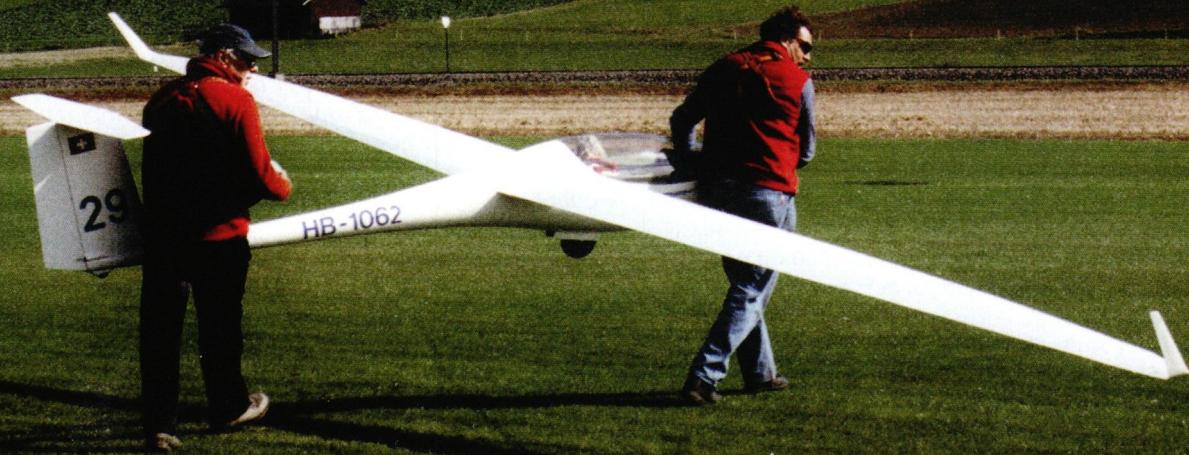
Here, we use the term “spar” to refer to the stringers that, together with the web, form the spar. The wings of a glider are subjected to two primary stresses: bending and torsion. The spar absorbs 90% of the bending stress, while the remaining 10% is absorbed by the wing skin. Torsional stress, on the other hand, is absorbed entirely by the wing skin2). In the “sandwich” construction of our models, the installation of a properly designed spar allows us to assume significant stresses due to bending. These stresses are primarily caused by the wing’s lift. During horizontal flight, the lift is approximately equal to the model’s weight. Since the lift and the weight of the wing are distributed across the entire wingspan, it can be assumed that the weight of the wing does not cause a bending moment in the wing (moment = product of a load and the lever arm at the pivot point). In contrast, the fuselage, which generates no lift, represents the load that the lift must counteract during horizontal flight. However, any
change in flight condition leads to a change in the load exerted by the fuselage due to centrifugal force (spiral flight, sharp turn, pull-up, etc.). Let’s remember once again that centrifugal force depends directly on the model’s weight and the square of its speed; for example, when the speed doubles, the weight increases fourfold. All too often, people fail to realize that our models—and especially those in the F3B category—are subjected to load factors that can exceed 30, meaning thirty times the model’s weight. As a reminder: The load factor g corresponds to the acceleration due to gravity; g = 10 corresponds to ten times the model’s weight. It should be noted here that large aircraft are not designed to withstand such high load factors as our models do, because the human body could not endure them for long—even with so-called anti-g suits. Based on these considerations, it becomes clear that the spars of our models must withstand very high stresses; the challenge, therefore, is to build them solidly, yet not too rigid or too light. This “squaring of the circle” was finally solved with the advent of carbon fibers. The strands (called rovings or layered threads) consist of an infinite number of carbon threads, which in turn are composed of individual fibers. The unit of measurement is the tex (1 tex = 1 g per 1,000 m) or the number of individual fibers; for example, NF24 = 24,000 individual filaments in the strand (NF = normal fiber). To manufacture a spar, a specific number of strands intended for the wing root must be used, calculated using a simple approximation formula:
| Number of NF24 rovings = 1.5 | Load factor × model weight × wingspan × profile height |
| - 1.5 is a safety factor used to increase the number of rovings, which are theoretically sufficient for the planned design. In full-scale aircraft construction, safety factors are prescribed to designers by the relevant authorities. - Load factor: Number g. For a large wing, g is estimated at 10–12; for an aerobatic glider, 20–25; and for an F3B model, 25–35. - Model weight: expressed in kg. - Model wingspan: expressed in m . - Airfoil height at the wing root: expressed in mm. |
I adapted the method by using carbon strips instead of strands as follows:
I would like to build a very large ASG-29 glider on a 1:2 scale, which means it will have a wingspan of 9 m. The estimated maximum weight is 29.999 kg, which allowed us to avoid having to appear before the OFAC panel of experts, who, for models weighing 30 kg or more, subject them to stress tests that would never occur during flight, only to ultimately issue a flight log in which all completed flights must be listed with detailed data. The selected airfoil, HQ 2.5/16–12, is relatively low-profile, with a thickness at the wing root of 58 mm, reduced to 55 mm for the calculations. The number of NF24 strands is therefore:
Number of NF24 rovings
$$= 1.5 \frac{12 \times 30 \times 9}{55} = 88$$
This formula, which is over 20 years old, was calculated for NF24 strands, a unit that has now almost fallen into obscurity and has been replaced by the tex. The Swiss-Composite3) catalog lists the equivalent: 24,000 filaments = 1,600 tex (1 km of this strand weighs 1,600 g). Thus, 88 strands of NF24 = 88 × 1,600 = 140,800 tex. To achieve this many tex, one must use multiple strands. According to this catalog, there is a Type 60K strand that contains 3,600 tex.
Therefore, the following is required:
$$\frac{140\,800}{3600}$$
= 39 Type 60K strands at the wing root
However, this technique is difficult to implement because a slot must be cut into the core whose volume corresponds exactly to the volume of 39 strands that have been impregnated with epoxy resin and have been defibrated by wetting. I used this technique for the construction of an 8.3-meter ASH-25: it is possible, but complicated. For the construction of my subsequent models, I built the spar separately and then inserted it into the core when the wing was being form-fitted. Instead of strands, I used flat carbon tapes consisting of several fiber bundles running lengthwise and held together crosswise by glass fibers, to make processing easier. The width of the spar is determined by the width of the tapes. I chose a tape with a weight of 350 g/m², 25 mm wide, 800 tex 12K—meaning it consists of 12 individual fiber bundles, each with a tex rating of 800. Such a tape therefore contains 800 × 12 = 9,600 tex. Since the
spar must contain 140,800 tex at the wing root, you therefore need
140,800
9,600
= 15 strips
The function of the spar is to absorb the bending moment of the wing, which is greatest at the wing root and decreases to zero at the wingtip. This decrease must therefore be taken into account. It can be calculated by dividing the wingspan into several sections and calculating the bending moment for each one. By plotting the resulting values (y-axis of the graph) as a function of the span (x-axis of the graph), one obtains not a straight line but a curve that asymptotically approaches the x-axis (asymptote). In practice, this means that the decrease in the number of
struts must follow the calculated curve. I avoided tedious calculations by drawing a graph on a 1:200 scale, on which I plotted the span of a wing—that is, 450 cm—on the x-axis, and the number of struts—15—on the y-axis. Using a graphing ruler, I drew a curve that slopes down toward the x-axis until it reaches a value of 2 struts at the wing tip. I then drew horizontal lines at each number of struts (from 1 to 15), as indicated on the y-axis. And at each point where the line intersected the curve, I drew a vertical line to the x-axis. This gave me the distribution of the decreasing number of struts across the wingspan, while keeping two struts at the wing tip (**see graph**).
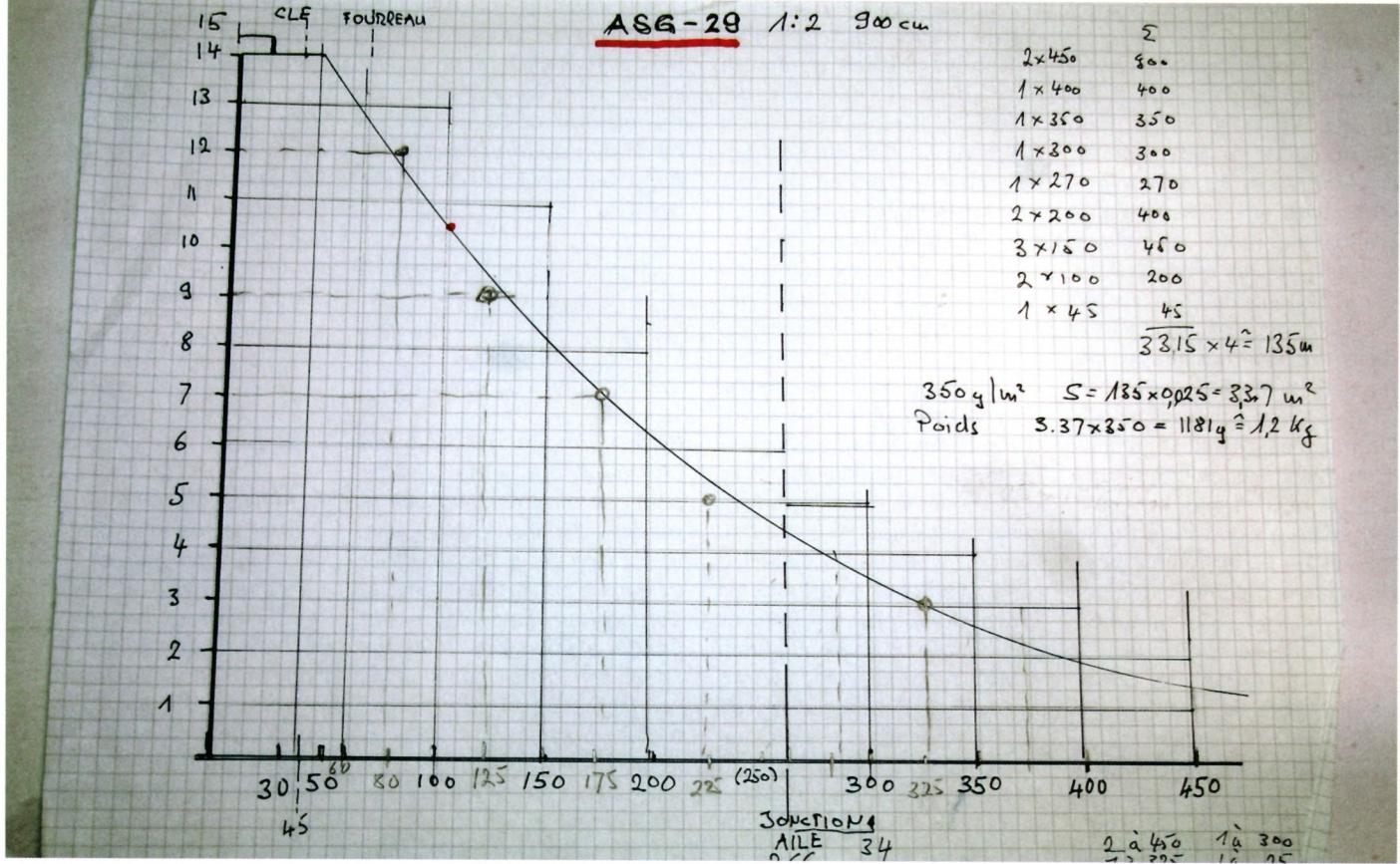
Since I separated the wing into two parts to make it easier to transport, I also designed each spar in two sections, with the first one measuring 266 cm in length. Screw two 300-cm-long aluminum angle profiles (thin curtain rods or similar) parallel to each other onto an 8×300-cm board covered with plastic sheeting, spaced apart by a distance equal to the width of the ribbon—in this case,
25 mm. Cut a wooden strip measuring 25 × 15 mm to the length of the spar and completely cover it with thin adhesive tape (brown packing tape). This strip must fit exactly between the two angle profiles. Mark the spacing on the base board starting from the wing root and indicate the corresponding number of strips. Apply formwork wax several times to the wooden
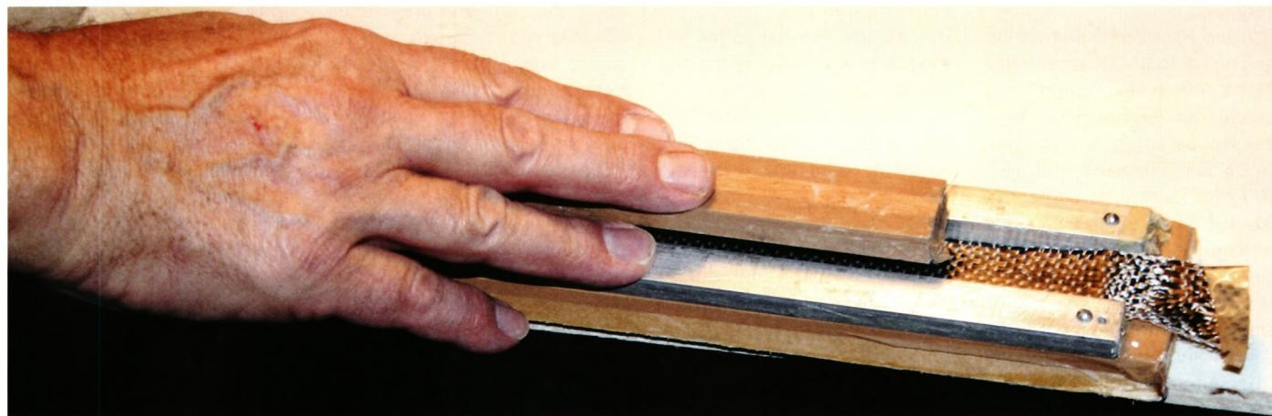
strip, the angle profiles, and the plastic sheeting with formwork wax several times. Secure the roll of carbon tape so it unrolls easily, and then lay the overlapping layers of tape between the two metal angle profiles, starting with the longest one (**see photo**): Dab them thoroughly with a brush dipped in epoxy resin to use as little resin as possible. Once all the strips have been laid down, press the wooden strip between the two angle profiles and slide the entire assembly into a vacuum bag. Use the vacuum pump at maximum power (–800 in this case). A high vacuum allows excess resin to be removed from the strips between the wooden strip and the angle profiles, resulting in a nearly optimal fiber-to-resin ratio. After the resin has polymerized, pull the spar out of its mold and let it cure on a flat surface for 3–4 days. Sometimes you have to unscrew the angle profiles to separate the spar, even after proper treatment with release wax. Now all that remains is to “sand down” the resin residue and remove the wax residue with pure benzene. You can also roughen the surfaces of the spar with 80-grit sandpaper to improve the resin’s adhesion when inserting it into the wing core.
For the rest of the construction, I make a cut in the top surface of the core that corresponds exactly to the tapered thickness of the spar, using a 25 × 300 mm sanding block (No. 80 sandpaper, glued to a 25 × 300 mm board). Use a hot wire to cut a groove corresponding to the width of the rib, cutting down to the middle of the core’s thickness. The top of the rib must be flush with the bottom surface of the spar cutout. Curing—
Let it dry. Follow the same steps for the underside. This method avoids any risk of deforming the profile, which can occur if you cut through the entire thickness of the core to insert a web in one piece. Coat a spar with epoxy resin and slide it into the cutout on the top side. Soak a double layer of carbon fiber fabric, oriented at 45°, 160 g/m², place it on the core, and lay the abachi veneer on top. Secure the assembly with a few strips of tape, flip the wing over, and repeat the same steps. Place the entire assembly, along with the mold, into a vacuum bag and turn on the pump.
This construction method allowed me to achieve a flying weight of 25.5 kg for the model, including 16 servos, 1,600 g of batteries, and 1,500 g of lead. I’m sorry, gentlemen of the OFAC, there’s nothing to inspect!
Dominique Baer
Photos: Ludovic Perrenoud
Translation into German:
Evi Wagner
(For more information: dominiquebaer@gmail.com)
1) U. Steenbuck, C. Baron. Modern Airfoil Design. modell-technik-berater, Verlag für Technik u. Handwerk, 1985.
2) See www.alexander-schleicher.de
Search for “spar installation”


News from HEBU

HORIZON HOBBY/LEMACO NEWS: MICRO OV-10 BRONCO 645 MM BY E-FLITE

PRIDE AND GOOD IDEAS
 Markus Nussbaumer

TEAM MANAGER "THIS" BOSSHARD
 Rodito Nussbaumer

YOU KNOW WHAT I MEAN? 125 YEARS OF THE SWISS AERO CLUB
 Emil Giezendanner

F3A EUROPEAN CHAMPIONSHIPS IN ST-MACAIRE, FRANCE
 Matthias Bosshard

ATOM, THE NEW DOUBLE-DECKER FROM CPLR
Matthias Bosshard
SUMMER FUN 2026 AT MG USTER
Martin Wunderli
TRY-OUT DAY AT MFV WETTINGEN
Urs Keller
What's New at Leomotion.com

52. 2026 ALPS CUP
Emil Giezendanner
TWIN TOWN PARTNERSHIP
Wolfgang Voeller
34th HAHNENMOOS ALPINE MODEL AIRPLANE CAMP
Res Dauwalder
CORSAIR F4U – A WARBIRD WITH A MEMORABLE LOOK
Jürgen Rosenberger, Jürgen Prinz
SMALL, MODEL-LIKE SAILBOATS
Res Dauwalder
WELCOME, NEW MEMBER!
Andrea Bolliger
FREE FLIGHT IN THE MIDDLE OF SUMMER
Urs Muntwyler
COUPE DES ALPES – OBSERVE AND LEARN
Rodito Nussbaumer
EURO CONTEST GLIDER ACRO TOUR AUSTRIA 2026

BY YOUTH, FOR YOUTH
Lorena Betschen
INSIGHTS INTO THE HISTORY OF SEAPLANES

THE PC-21 STORY
Emil Giezendanner
NEWS FROM HEBU
 Julia Bucher

FROM 0 TO 100
Markus Nussbaumer
MEMORIES
Wolfgang Völler
NOS REGION – A HUB FOR ELECTRIC AVIATION
Emil Giezendanner
DO YOU KNOW WHAT I MEAN IN THE LAND OF SMILES?
Emil Giezendanner
Have you almost forgotten about aircraft that take off and land vertically?
Emil Giezendanner