
Noise Control in Model Aviation
The Model Aircraft Committee of Region 2 of the Swiss Aero Club (Mr. E. Wellenzohn, Chairman) requested that the Federal Aviation Office conduct noise measurements on model aircraft so that guidelines and recommendations could be developed to control noise emissions from the models.
The Model Aircraft Committee of Region 2 of the Swiss Aero Club (Mr. E. Wellenzohn, Chairman) requested that the Federal Aviation Office conduct noise measurements on model aircraft so that guidelines and recommendations can be developed to address the noise emissions from these models. From the Aero-Club’s perspective, it is important to resolve the noise issue with model aircraft so that this type of recreational activity is not unduly restricted by Article 79 of the Air Traffic Regulations and so that permissible limits can be established for competition models at the World Championships from September 8–13, September 1975 at Belpmoos.
Meteorological data:
Measurements a–d | Measurement e | |
QNH | 1022 mb | 1022 mb |
Temperature | 10° C | 8° C |
rel. H. | 62% | 80% |
Wind | var. 0–4 kts | var. 0–4 kts |
Aircraft studied:
Operating conditions and equipment of the models during sound measurements:
Stationary measurement on FU-27, type: Marabu-Trainer with Webra-Speed engine; RPM at full throttle 11,800 with original exhaust silencer
Stationary measurement on FU-27: RPM at full throttle 11,300 with special exhaust silencer (Kö muffler)
In-flight measurement: 2 m above ground at a lateral distance of 25 m from the microphone with the FU-27; RPM at full throttle: 11,300 with a special exhaust silencer (Kö muffler)
Stationary measurement on BE-38, model: Senior Falcon with Enya III engine; with original exhaust silencer, RPM at full throttle: 11,000
Stationary measurement on BE-38 with special exhaust silencer; RPM at full throttle: 10,700
For the measurement method, see the section following the summary
Measuring equipment used:
1" B+K Type 4131 microphone
B+K Type 2112 third-octave/octave band analyzer
B+K Type 2305 sound level recorder
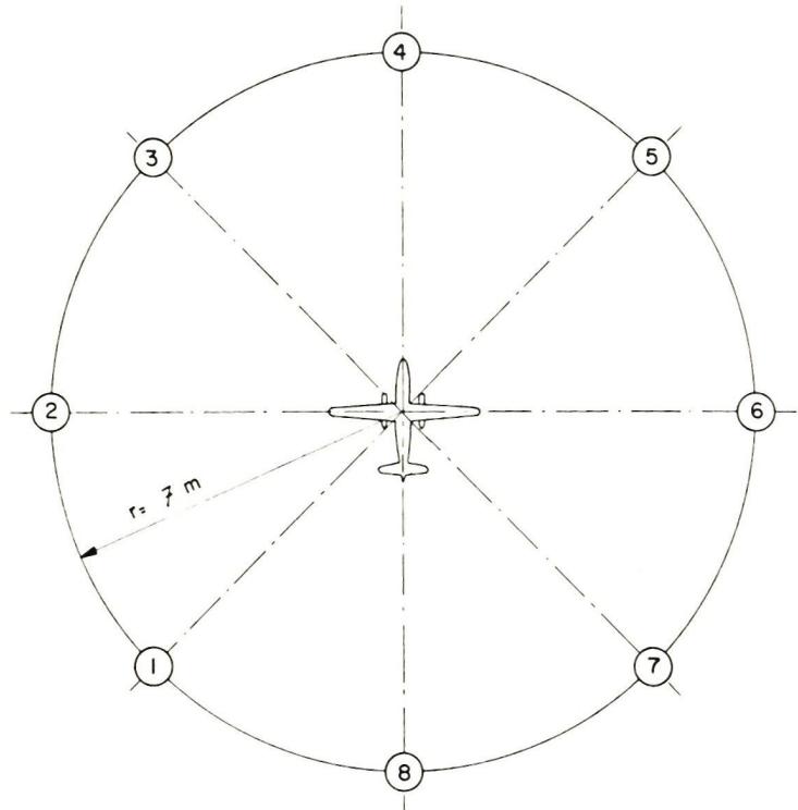
- ①—⑧ Measurement points on a circle with a radius
of 7 m; angle between the measurement points: 45 degrees
; ground conditions: mowed grass
can be seen in the tables and graphs provided, although only those that are most important and easiest for us to understand have been included here.
Assuming that the desired permissible noise levels in a quiet residential zone—as recommended in the report by the Federal Expert Commission—are not exceeded, this means that the center of the flight zone (with a flight radius of 300 m) for a loud model such as 2a must be located in an uninhabited area with a circular area of 2–2.5 km² or a diameter of 1,600–1,800 m, so that a sound level of 45 dB(A) is not exceeded (applies to Zone II, “quiet residential zone”). Finding such an area is likely to remain a pipe dream for many modelers. However, specialized silencers are already commercially available today that make it possible to significantly reduce noise at the source. (See the table below).
The noise reduction achieved by special silencers on the measured models is 6–8 dB(A), reducing the affected area by 50%, which still corresponds to a circle with a diameter of 1,200 m.
Provided that we can maintain a minimum distance of 600 m to the nearest residential area, an average value of 82 dB(A) across the 8 positions—as determined by the measurement method used—can be recommended as the target limit. For the Model Aerobatics World Championship, the approved limit of 82 dB(A) at a distance of 10 m—which has already been published in Aero Revue—can be supported, corresponding to 84 dB(A) at 7 m.
Regarding flight measurements, it should be noted that, due to the inability to maintain a precise flight path, they are not suitable for determining a comparable sound level.
We recommend the following measurement method:
- a) — 1–8 measurement points on a circle with a radius of 7 m. Angle between measurement points: 45° (see 1.0)
- The model aircraft is secured to a rotating stand with the smallest possible platform (400 x 250 mm) at a height of 1.20 m above the ground
- Microphone height above the ground: 1.20 m
- b) — The sound level measurement is performed at full throttle
- At all 8 positions, the A-weighted sound level in dB(A) units is measured sequentially using a suitable sound level meter, with the “slow” time constant selected.
- c — Ground conditions: mowed grass
- There must be no sound-reflecting objects, such as buildings, walls, etc., within a 30-meter radius of the measurement point
- At wind speeds exceeding 2 m/s (4 knots), the measurement line between the sound source and the microphone must be aligned with the wind axis. At wind speeds exceeding 5 m/s (10 knots), sound measurements must not be performed
- d) The sound level meters must comply with the specifications of the International Electrotechnical Commission (IEC), Doc. 179, “Precision Sound Level Meters.”
We recommend the following limit values:
- a) The energy-weighted average must be calculated from the 8 measurement positions; this average should not exceed 82 dB(A). (78 dB(A) would be desirable.)
Federal Aviation Authority, Flight Equipment Section
Model | Exhaust system | Measured average values | Calculated average values | ||||
dB (lin) | dB(A) | PNdB | dB(lin) | dB(A) | PNdB | ||
FU-27 | Original | 88 | 88 | 100 | 52 | 51 | 61 |
FU-27 | Special | 83 | 81 | 94 | 48 | 45 | 49 |
BE-38 | Original | 86 | 86 | 98 | 51 | 49 | 59 |
BE-38 | Special | 80 | 78 | 91 | 46 | 43 | 48 |


News from HEBU

EURO CONTEST GLIDER ACRO TOUR AUSTRIA 2026

TEAM MANAGER "THIS" BOSSHARD
 Rodito Nussbaumer

YOU KNOW WHAT I MEAN? 125 YEARS OF THE SWISS AERO CLUB
 Emil Giezendanner

TRY-OUT DAY AT MFV WETTINGEN
Urs Keller
F3A EUROPEAN CHAMPIONSHIPS IN ST-MACAIRE, FRANCE
 Matthias Bosshard

HORIZON HOBBY/LEMACO NEWS: MICRO OV-10 BRONCO 645 MM BY E-FLITE

PRIDE AND GOOD IDEAS
 Markus Nussbaumer

BY YOUTH, FOR YOUTH
Lorena Betschen
34th HAHNENMOOS ALPINE MODEL AIRPLANE CAMP
Res Dauwalder
52. 2026 ALPS CUP
Emil Giezendanner
TWIN TOWN PARTNERSHIP
Wolfgang Voeller
ATOM, THE NEW DOUBLE-DECKER FROM CPLR
Matthias Bosshard
CORSAIR F4U – A WARBIRD WITH A MEMORABLE LOOK
Jürgen Rosenberger, Jürgen Prinz
SUMMER FUN 2026 AT MG USTER
Martin Wunderli
What's New at Leomotion.com

THE PC-21 STORY
Emil Giezendanner
COUPE DES ALPES – OBSERVE AND LEARN
Rodito Nussbaumer
SMALL, MODEL-LIKE SAILBOATS
Res Dauwalder
WELCOME, NEW MEMBER!
Andrea Bolliger
FREE FLIGHT IN THE MIDDLE OF SUMMER
Urs Muntwyler
INSIGHTS INTO THE HISTORY OF SEAPLANES

NEWS FROM HEBU
 Julia Bucher

FROM 0 TO 100
Markus Nussbaumer
MEMORIES
Wolfgang Völler
NOS REGION – A HUB FOR ELECTRIC AVIATION
Emil Giezendanner
DO YOU KNOW WHAT I MEAN IN THE LAND OF SMILES?
Emil Giezendanner
A SPECTACULAR F3A WORLD CUP IN THE PRINCIPALITY OF LIECHTENSTEIN
Emil Giezendanner