
An extraordinary replica of the HB-ZKE
The MD-902 Explorer is an eight-seat, twin-engine turbine-powered helicopter manufactured by the U.S. company MD Helicopters. Notar is a system developed by McDonnell Douglas for torque compensation in helicopters without the typical tail rotor configuration. The United States Coast Guard operates this model under the name MH-90 Enforcer.
The MD-902 HB-ZKE was in service with Fuchs Helicopter in Schindellegi, Switzerland, from April 2009 to June 2014. On several occasions during the winter, the HB-ZKE was leased to Heli Austria and served as the “Martin Rescue Helicopter” in Saalbach-Hinterglemm. Enrico Gianni built a full-scale model of “Martin” from a fuselage kit by Vario.
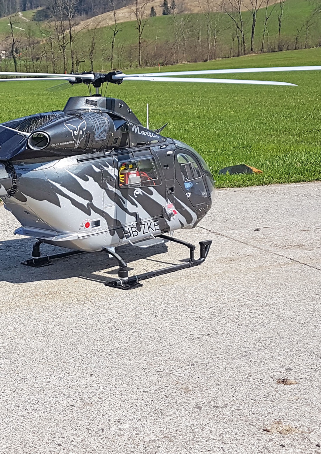
McDonnell Douglas presented the first studies of the MD Explorer in February 1988 as the MDX. However, the decision to proceed with development was not made until a year later. The production model was initially designated the MD-900 or MD-901/MD-902, a name that was later changed to MD Explorer. The first prototype took off on its maiden flight on December 18, 1992. The first production helicopter took off on August 3, 1994, and received its FAA certification on December 2, 1994. The first delivery took place that same month. European certification followed in 1996. The first helicopter of the improved MD-902 model—equipped with more powerful engines, improved heating, and an EFIS, and certified for night flight—was delivered to Japan in May 1998 (first flight in 1997). By January 2000, 57 aircraft of this series were already in service. An armed military variant, the MH-90 Enforcer, is now also available.
The airframe and the five rigid rotor blades are made primarily of carbon-fiber composites. Initially, Turbomeca engines were planned for propulsion, but this was later abandoned in favor of the throttled Pratt & Whitney PW206A, which is equipped with a digital control system (FADEC—Full Authority Digital Engine Control).
Notar (No Tail Rotor) is a system developed by McDonnell Douglas to provide torque compensation for helicopters that lack the typical tail rotor configuration. The patent is owned by Boeing.
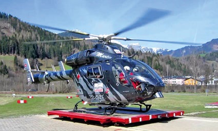
The test platform was a Hughes OH-6, in which the tail boom had been reinforced and a shrouded propeller blew air into the boom. This air flowed out again through a longitudinal slot on the lower right side of the boom. An adjustable nozzle was mounted at the tail to control the thrust. The first flight of this system took place on December 17, 1981. Similar systems, which typically utilized the engine’s exhaust flow, had already been tested in the 1940s on the Cierva W.9 and the Hiller J-5, and in the 1950s on the Aerotecnica AC-12 Norelle.
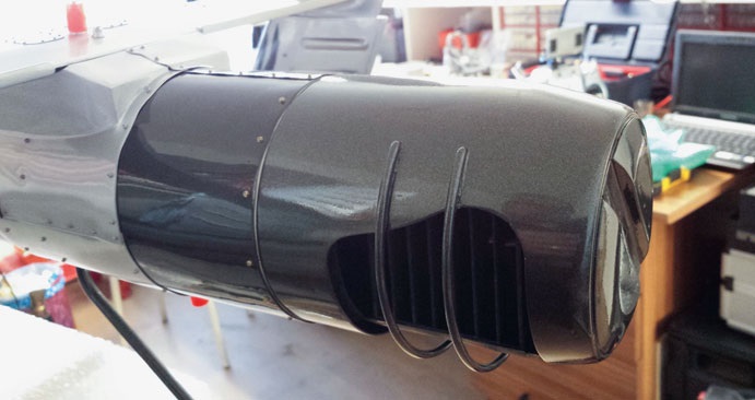
Operating Principle. In principle, in a helicopter with only one main rotor, the torque generated by the rotor must be balanced to counteract rotation of the fuselage and to enable the helicopter to be controlled around the vertical axis (yaw axis). This is usually achieved by a horizontally acting tail rotor; however, the Notar system generates the counterforce through a directed jet of air (thrust) that exits through a variable control nozzle at the end of the boom. This effect is supported by additional outlet nozzles positioned only on one side along the tail boom. The air flowing out from these nozzles guides the downdraft from the main rotor around the curve of the tail boom. This utilizes the Coandă effect (the term “Coandă effect” is a collective term for various phenomena that are not causally related but suggest a tendency for a gas jet or liquid flow to “run along” a convex surface, rather than separating from it and continuing in its original direction of flow). This effect is utilized in the flow around a cylindrical tube with a one-sided, slit-shaped outlet tangential to the tube’s surface. In combination with the flow around the pipe, this creates circulation with a pressure side and a suction side. This generates an additional force opposed to the main rotor’s torque, which stabilizes the fuselage in the longitudinal direction. The advantages of the Notar system include a lower risk to people in the takeoff and landing zone, as well as reduced noise levels, since the propeller is located inside the fuselage and there is no noise-intensive turbulence between the main and tail rotors.
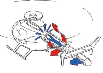
Unfortunately, an MD-902 gained notoriety in Austria in 2017. During a rescue mission at dusk on August 1, 2017, on the Grossglockner just below the Erzherzog-Johann-Hütte, an MD-902 operated by Heli Austria crashed. It spun around its vertical axis, touched the ground, tipped to one side, and sheared its rotor blades off on impact. The pilot, flight paramedic, and patient on board were not injured; the emergency physician, who was outside and initially standing next to the helicopter’s cargo hatch, sustained minor injuries.
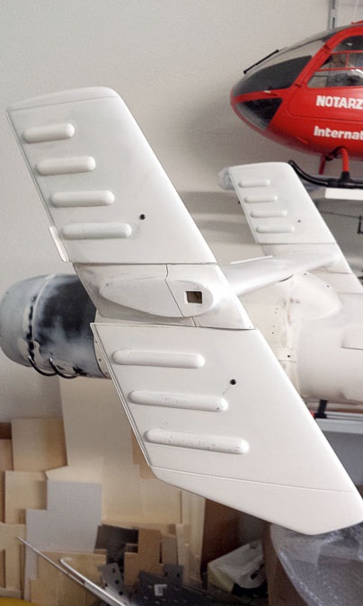
Throughout his entire career—spanning 45 years—Enrico Gianni worked with airplanes and helicopters. At the aircraft factory in Emmen (now Ruag), he worked on the Dassault Mirage III S and RS, the Aérospatiale ALIII, the BAE Hawk, the Aérospatiale Super Puma, and the McDonnell Douglas F/A-18. He lives in the beautiful region of Central Switzerland—more specifically, in Obwalden—and has been a member of the Lucerne Model Flying Club for years; the club is based at the Emmen military airfield. Enrico Gianni caught the model-building bug in 2003 during the model flying days in Hausen. He gained his first experience with model helicopters with a Mikado Logo 16, and his first scale project was a Hirobo EC-135. Unfortunately, the size and design of this model made it nearly impossible to build true-to-scale replicas. This prompted Enrico to look for another model that would meet his high standards and requirements. During his search, he happened to come across the MD-902 from Fuchs Helikopter, which was in service at the time in Saalbach-Hinterglemm, Austria. This was exactly the one he wanted. He quickly gathered the necessary documentation, which is essential for a 100 percent scale replica.
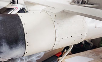
While searching for a suitable fuselage that was also of a certain size, Enrico Gianni found what he was looking for at Vario Helicopters. From the outset, however, it was clear to him that in many details, the fuselage’s design did not correspond to the original in any way. In other words, a great deal of work still had to be put into refinements or complete modifications. This also explains the long construction period of four years. In this report, we’ll discuss some of the most notable changes that made the model what it is today.
The model kit features a fully symmetrical vertical stabilizer, whereas the actual aircraft has a semi-symmetrical one. The vertical stabilizer consists of two parts—an upper and a lower section—which are mounted on a support attached to the horizontal stabilizer. This allows the angle of attack to be adjusted. On the original, the upper part of the tail unit features four vertical stabilizers—not just three as on the kit model—and the shape of these added stabilizers is also different. The scale conversion required cutting into the horizontal stabilizer to correct its shape (new negative airfoil profile). It was also necessary to extend it by 70 mm, as the vertical stabilizers are positioned further outward than intended in the kit. On the upper surfaces of the vertical stabilizers, the inner and outer vertical stabilizers were removed and replaced with ones that match the original in both shape and number. Concurrent with this modification, the center sections on the left and right had to be redesigned (a special twisted shape). This first required building a corresponding negative mold to manufacture the new fiberglass components. A carbon rod was integrated into each of the new vertical stabilizer mounts to serve as a mounting point for the vertical stabilizer. On the horizontal stabilizer mount at the boom, the access panels were recreated to match the prototype. New negative molds were also produced for these panels.
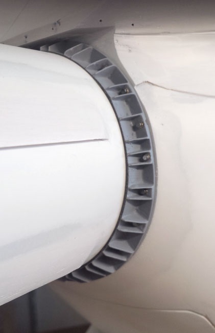
Another, somewhat larger modification was necessary for the connection of the tail boom to the fuselage. On the original, the tail boom is bolted to the fuselage using a solid outer rib/support. It had to look that way—that was the builder’s request. →
| MD-902 Explorer | Prototype | Model |
| Crew | 1–2 | – |
| Passengers | 6–7; during rescue missions, a doctor and 2 stretchers | – |
| Max. takeoff weight | 2,948 kg (3,130 kg with external load) | 11.5 kg |
| External load | 1,360 kg (towed load) | – |
| Engines | 2× Pratt & Whitney Canada PW206E, 373 kW each | Strecker electric motor, Kontronik 120PRO controller |
| Fuel capacity | 730 l | 2× 6S 8,000 mA battery |
| Fuselage length | 10.39 m | 1.73 m |
| Length overall | 12.37 m (rotor spinning) | 2.23 m |
| Width | Cabin (exterior) 1.62 m | 0.4 m |
| Height with tail unit | 3.66 m | 0.6 m |
| Rotor diameter | 10.34 m | 1.68 m |
| Rotor speed | 392 rpm | 1,450 rpm |
| Cruising speed | 252 km/h | – |
| Range | up to 600 km | – |
| Max. rate of climb | 10–14 m/sec | – |
In order to attach the outer strut, a surface had to be created at the end of the fuselage, which meant: removing the fiberglass tube that had already been embedded in resin to accommodate the tail boom, shortening the fuselage by 10 mm, repositioning the fiberglass tube, and embedding it in resin again!
The Frame: First, the outer strut ring was sketched to scale on paper after measuring the prototype. This ring was cut out of a 1.5 mm thick fiberglass-reinforced plastic (FRP) sheet, and the 80 mm diameter tube was also fabricated from FRP. To properly position the ring-to-tube connecting elements, a jig had to be fabricated. Twenty-four M2 screws were screwed into the frame, which also ensure that the boom is securely fastened to the fuselage. It was no longer possible to determine exactly how many hours of work this took. It should also be noted here that the very first ring produced fit perfectly.
Unlike the MD-900, the tail pipe of the MD-902 has been extended behind the horizontal stabilizer. Compared to the prototype, the tail boom is 70 mm too short at the correct scale. These missing 70 mm had to be fabricated by hand.
To ensure the fuselage looked authentic, approximately 2,800 rivets were installed. These rivets were inserted one by one into their respective positions using 0.7-mm drill holes. Unfortunately, the windows included with the kit are too small, and some of them lack the proper curvature. The windows are also too small for the cutouts. To get as close as possible to the original here as well, Enrico Gianni decided to make his own molds so he could produce the windows. The discs included with the kit were used to create a positive mold, which, after some reworking, was used to deep-draw the new discs. It was a lot of work, but it was definitely worth it.
Many other minor and major modifications to the fuselage—such as air intakes and shape adjustments in the forward dome area—make this model an almost 100 percent replica.
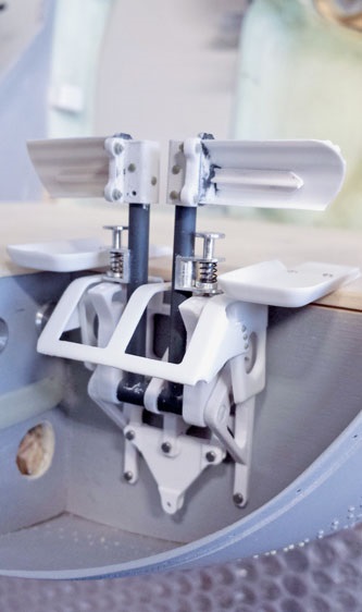
The Vario fuselage is designed so that the guides for the sliding doors are mounted on the outside. That had to be changed as well. Just like on the real aircraft, openings were cut into the fuselage, and the new rails—fabricated from ABS profile—were fitted at the top and bottom, along which the aluminum-milled door guides now run. The functional covers over the engines feature homemade ABS hinges—even the Fokker pin is included. The numerous small brackets (Fortex effect) on the tail boom were painstakingly crafted to match the prototype. The access steps on the landing skids, as well as the plastic connectors between the bracket and the skids, were realistically milled from aluminum and formed from aluminum sheet. Of course, this replica also includes the rear damper, located above the skid, and the anti-sink guard.
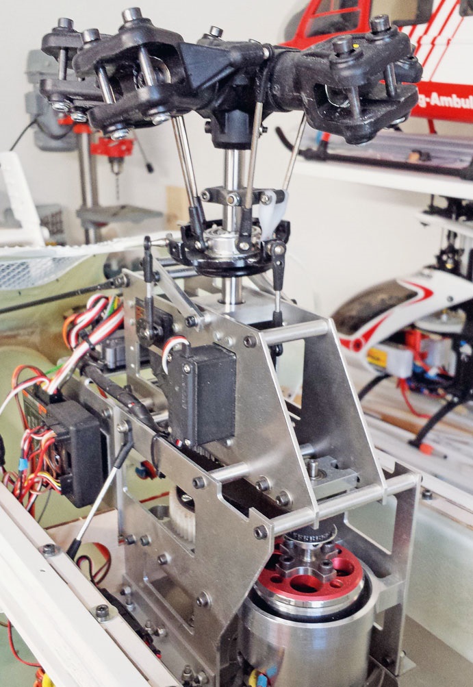
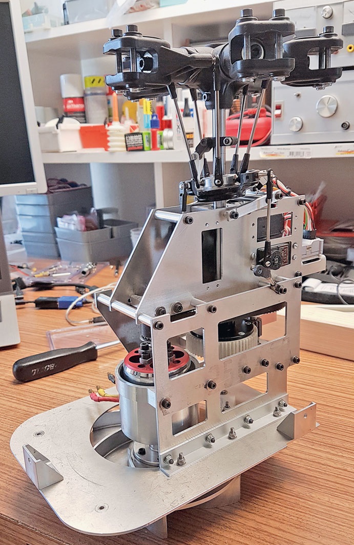
From the very beginning, Enrico Gianni was certain that the propulsion system and the fan for the tail section had to form a single unit. But the propulsion system also had to be electric. During these deliberations and investigations, which took place in 2011, Vario initially offered only a gasoline-powered system. However, this was by no means an option. Through extensive research, he made contact with Sandy Jaffy in the U.S. Jaffy was already experimenting with an electromechanical system in which the fan for the tail control was also integrated into a single unit. That marked the start of the project to build his own electromechanical system. With Sandy’s expertise as a foundation, Enrico set out to design the custom mechanism. The transmission is a two-stage system. Power is transferred from the motor to the second stage via a timing belt, and from there to the rotor shaft via a gear train. The radial fan, from Vario, is driven by the motor’s drive shaft. The timing belt pulley is driven via a flanged shaft on the rear of the motor. The Strecker RS 435-30 motor offered this capability. The tail air control is forced into the tail tube by the fan through a duct. Controlled by an analog servo, the flap that regulates the airflow for the tail control is activated. The cutouts for the three Futaba servos were positioned on the sides of the mechanical assembly to ensure a direct and straight linkage to the tail pulley. A Kontronik Jive 120 PRO HV is used as the ESC. The 3SX from Bavarian Demon serves as the attitude stabilization system.
After completing the model and assembling all the components, the builder decided—since so many changes, some of them significant, had been made to the fuselage—to conduct the maiden flight with the airframe still in its rough-built state. The fact that significant changes had been made to the horizontal and vertical stabilizers, the length of the tail boom, and the airframe itself led to this decision.
However, the concerns were unfounded, and the model, weighing ten kilograms, flew as steady as a “board.” The tail surfaces and canopy were also free of any noticeable vibrations. The tail response was more than satisfactory as well; precise and responsive tail control was a reality from the very beginning. Based on previous experience with motor and ESC cooling, the measured temperatures were within the normal range. This is due to the ESC’s attached heat sink, which is located directly in the airflow of the radial fan. The motor is also additionally cooled by this airflow.
During another test flight, an overview of power consumption and performance was assessed. Something surprising came to light here—the fan consumes 60% of the power, while flying accounts for only 40%. The current remains constant between 55 and 60 amps.
Armed with these findings and results, we were able to confidently begin the painting and scale conversion.
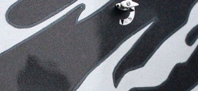
After attaching the last scale parts to the model, it was ready to be sanded and primed. The design was copied from a side view photo of the original, resized to the correct dimensions, and then cut out on a plotter.
The most time-consuming part was masking off the areas and positioning the adhesive film correctly.
First, the gray-blue metallic paint was sprayed onto the trim, which, once the painting was complete, would surround the silver metallic ornaments. Next came the anthracite metallic paint, followed by the silver metallic.
Lettering, details, and the license plate number rounded out the paintwork before the clear coat was applied. The “Martin” lettering, which was applied when the car was in use in Austria, has also been added. It was still in place when Enrico Gianni took the photographs in 2010, so this detail absolutely had to be included.
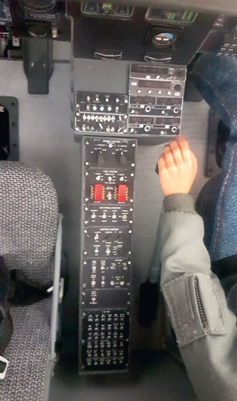
Without a cockpit and add-ons such as antennas, headlights, and lighting, a model is only half a model. The builder left nothing to chance with the cockpit either. For example, the foot pedals are fully functional. And all the switches and screens in the cockpit are positioned exactly where they would be on the original HB-ZKE and feature the correct color scheme. The lighting system, with all its lights and headlights, is an exact replica of the prototype. The highlight is the searchlight, which—in addition to its extend-retract function—can also be swiveled left and right. The latest generation of Luxeon emitters provides the necessary lighting effect. The exterior also features numerous details, even small ones—such as DZUS® quick-release fasteners, antennas in all variations, and sliding windows in the pilot’s door.
| MD-902 Explorer | Original | Model |
| Crew | 1–2 | – |
| Passengers | 6–7; in rescue operations, one doctor and two stretcher bearers | – |
| Max. takeoff weight | 2,948 kg (3,130 kg with external load) | 11.5 kg |
| Payload/External load | 1,360 kg (cargo capacity) | – |
| Powerplant/Engines | 2× Pratt & Whitney Canada PW206E: 373 kW each | Strecher electric motor, Kontronik 120PRO controller |
| Fuel/Fuel Capacity | 730 l | 2× 6S 8,000 mA battery |
| Fuselage length | 10.39 m | 1.73 m |
| Overall length | 12.37 m (rotor spinning) | 2.23 m |
| Width | Cabin (exterior) 1.62 m | 0.4 m |
| Height with tail unit | 3.66 m | 0.6 m |
| Rotor diameter | 10.34 m | 1.68 m |
| Rotor speed | 392 rpm | 1,450 rpm |
| Cruising speed | 252 km/h | – |
| Range | up to 600 km | – |
| Max. vertical speed/Max. climb rate | 10–14 m/sec | – |
Once the model was completed, the second maiden flight was imminent. But no one could have foreseen that problems would arise at this point. The weight of the airframe, which had been 11.5 kilograms, had increased to just under twelve kilograms after completion. The additional weight of 1½ kilograms required a pitch angle of plus 7° in hover and a maximum rotational speed of approximately 1,550 rpm for the main rotor, which has a diameter of 1.60 meters.
A pitch angle of 7° in hover is too high. But what now?
After extensive calculations and research, the initial problems were resolved through various optimizations, such as a new rotor head (screw-in blade mount), a 5-blade set from M-Blades, a Scorpion motor, and adjustments to the gearbox. Key factors here are the interplay between battery voltage, gear ratio, and motor RPM—and, particularly important for the MD-902, the airflow generated for the tail control.
Over the course of about four years, Enrico Gianni has created a one-of-a-kind model of the MD-902. Details that were, in some cases, considered impossible to recreate were brought to life 100 percent. When asked if he would build the model again and go through all that effort, Enrico answers without hesitation: “Yes, definitely. There are still a few things that could be done if I were to build it again. But I could also incorporate a few small details that were left out of this model.”


News from HEBU

TEAM MANAGER "THIS" BOSSHARD
 Rodito Nussbaumer

YOU KNOW WHAT I MEAN? 125 YEARS OF THE SWISS AERO CLUB
 Emil Giezendanner

HORIZON HOBBY/LEMACO NEWS: MICRO OV-10 BRONCO 645 MM BY E-FLITE

PRIDE AND GOOD IDEAS
 Markus Nussbaumer

34th HAHNENMOOS ALPINE MODEL AIRPLANE CAMP
Res Dauwalder
TRY-OUT DAY AT MFV WETTINGEN
Urs Keller
F3A EUROPEAN CHAMPIONSHIPS IN ST-MACAIRE, FRANCE
 Matthias Bosshard

52. 2026 ALPS CUP
Emil Giezendanner
ATOM, THE NEW DOUBLE-DECKER FROM CPLR
Matthias Bosshard
SUMMER FUN 2026 AT MG USTER
Martin Wunderli
What's New at Leomotion.com

THE PC-21 STORY
Emil Giezendanner
COUPE DES ALPES – OBSERVE AND LEARN
Rodito Nussbaumer
TWIN TOWN PARTNERSHIP
Wolfgang Voeller
EURO CONTEST GLIDER ACRO TOUR AUSTRIA 2026

BY YOUTH, FOR YOUTH
Lorena Betschen
CORSAIR F4U – A WARBIRD WITH A MEMORABLE LOOK
Jürgen Rosenberger, Jürgen Prinz
SMALL, MODEL-LIKE SAILBOATS
Res Dauwalder
WELCOME, NEW MEMBER!
Andrea Bolliger
FREE FLIGHT IN THE MIDDLE OF SUMMER
Urs Muntwyler
INSIGHTS INTO THE HISTORY OF SEAPLANES

NEWS FROM HEBU
 Julia Bucher

FROM 0 TO 100
Markus Nussbaumer
MEMORIES
Wolfgang Völler
NOS REGION – A HUB FOR ELECTRIC AVIATION
Emil Giezendanner
DO YOU KNOW WHAT I MEAN IN THE LAND OF SMILES?
Emil Giezendanner
A SPECTACULAR F3A WORLD CUP IN THE PRINCIPALITY OF LIECHTENSTEIN
Emil Giezendanner